Lenovo ThinkPad W530 Hardware Maintenance Manual - Page 116
Antenna kit and LCD rear cover assembly, Wireless WAN antenna, AUX blue
 |
View all Lenovo ThinkPad W530 manuals
Add to My Manuals
Save this manual to your list of manuals |
Page 116 highlights
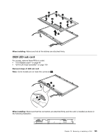
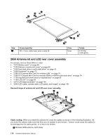
9 10 9 Step 9 Screw (quantity) M2 × 3 mm, wafer-head, nylon-coated (4) 9 10 9 Color Silver Torque 0.181 Nm (1.85 kgfcm) 2050 Antenna kit and LCD rear cover assembly For access, remove these FRUs in order: • "1010 Battery pack" on page 66 • "1030 Memory module slot cover" on page 68 • "1050 Hard disk drive or solid state drive" on page 70 • "1060 Keyboard" on page 72 • "1080 PCI Express Mini Card for wireless LAN" on page 76 • "1090 PCI Express Mini Card for wireless WAN or mSATA solid state drive" on page 78 • "1100 ExpressCard blank bezel or ExpressCard" on page 82 • "1180 LCD unit" on page 94 • "2010 LCD bezel assembly" on page 104 • "2040 LCD cable, camera cable, LCD panel, and hinges" on page 106 Removal steps of antenna kit and LCD rear cover assembly 3 1 3 2 2 3 3 2 2 1 Cable routing: When you install the antenna kit, route the cables as shown in the following illustration. As you route the cables, make sure that they are not subject to any tension. Tension could cause the cables to be damaged by the cable guides, or a wire to be broken. a Wireless WAN antenna, AUX (blue) 110 Hardware Maintenance Manual
-
 1
1 -
2
-
3
-
4
-
5
-
6
-
7
-
8
-
9
-
10
-
11
-
12
-
13
-
14
-
15
-
16
-
17
-
18
-
19
-
20
-
21
-
22
-
23
-
24
-
25
-
26
-
27
-
28
-
29
-
30
-
31
-
32
-
33
-
34
-
35
-
36
-
37
-
38
-
39
-
40
-
41
-
42
-
43
-
44
-
45
-
46
-
47
-
48
-
49
-
50
-
51
-
52
-
53
-
54
-
55
-
56
-
57
-
58
-
59
-
60
-
61
-
62
-
63
-
64
-
65
-
66
-
67
-
68
-
69
-
70
-
71
-
72
-
73
-
74
-
75
-
76
-
77
-
78
-
79
-
80
-
81
-
82
-
83
-
84
-
85
-
86
-
87
-
88
-
89
-
90
-
91
-
92
-
93
-
94
-
95
-
96
-
97
-
98
-
99
-
100
-
101
-
102
-
103
-
104
-
105
-
106
-
107
-
108
-
109
-
110
-
 111
111 -
 112
112 -
 113
113 -
 114
114 -
 115
115 -
 116
116 -
 117
117 -
 118
118 -
 119
119 -
 120
120 -
 121
121 -
122
 |
 |
