Linksys SPA921 Cisco Small Business IP Phone SPA9X1 Administration Guide - Page 30
Front Panel, Back Panel, SPA942
 |
UPC - 745883570799
View all Linksys SPA921 manuals
Add to My Manuals
Save this manual to your list of manuals |
Page 30 highlights
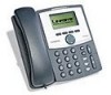
Chapter 2 Getting Started Figure 2-5 SPA941 Linksys 900 Series IP Phones Front Panel The following tables describe the status indicators and controls on the front of the device and the ports on the back panel of the device. Back Panel Feature LCD display Telephone keypad Navigation button Soft keys 1-4 Line status indicators 1-4 Function Lists device status and configuration options. Enters numeric digits for initiating a call or for entering configuration information. Scrolls between display and configuration options in the LCD display. Selects options on the LCD display. Displays status of each extension. SPA942 Port Phone jack Ethernet ports Power Function Connects to the handset. Connects to the SPA9000 through a local switch. Connects to the 5-volt power supply. The SPA942 is similar to the SPA941, but provides two Ethernet ports for connecting to the LAN and supports Power over Ethernet (see Figure 2-6). The PA100 power supply must be ordered separately if you are not using a PoE switch. See the table for SPA941. Firmware Version 5.1 Linksys IP Phone Administrator Guide 2-7
-
 1
1 -
2
-
3
-
4
-
5
-
6
-
7
-
8
-
9
-
10
-
11
-
12
-
13
-
14
-
15
-
16
-
17
-
18
-
19
-
20
-
21
-
22
-
23
-
24
-
 25
25 -
 26
26 -
 27
27 -
 28
28 -
 29
29 -
 30
30 -
 31
31 -
 32
32 -
 33
33 -
 34
34 -
 35
35 -
36
-
37
-
38
-
39
-
40
-
41
-
42
-
43
-
44
-
45
-
46
-
47
-
48
-
49
-
50
-
51
-
52
-
53
-
54
-
55
-
56
-
57
-
58
-
59
-
60
-
61
-
62
-
63
-
64
-
65
-
66
-
67
-
68
-
69
-
70
-
71
-
72
-
73
-
74
-
75
-
76
-
77
-
78
-
79
-
80
-
81
-
82
-
83
-
84
-
85
-
86
-
87
-
88
-
89
-
90
-
91
-
92
-
93
-
94
-
95
-
96
-
97
-
98
-
99
-
100
-
101
-
102
-
103
-
104
-
105
-
106
-
107
-
108
-
109
-
110
-
111
-
112
-
113
-
114
-
115
-
116
-
117
-
118
-
119
-
120
-
121
-
122
-
123
-
124
-
125
-
126
-
127
-
128
-
129
-
130
-
131
-
132
-
133
-
134
-
135
-
136
-
137
-
138
-
139
-
140
-
141
-
142
-
143
-
144
-
145
-
146
-
147
-
148
-
149
-
150
-
151
-
152
-
153
-
154
-
155
-
156
-
157
-
158
-
159
-
160
-
161
-
162
-
163
-
164
-
165
 |
 |
