Linksys SPA921 Cisco SPA9000 Voice System Web-UI Based Product Installation an
Linksys SPA921 - Cisco - IP Phone Manual
 |
UPC - 745883570799
View all Linksys SPA921 manuals
Add to My Manuals
Save this manual to your list of manuals |
Linksys SPA921 manual content summary:
- Linksys SPA921 | Cisco SPA9000 Voice System Web-UI Based Product Installation an - Page 1
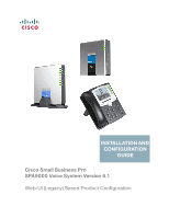
INSTALLATION AND CONFIGURATION GUIDE Cisco Small Business Pro SPA9000 Voice System Version 6.1 Web-UI (Legacy) Based Product Configuration - Linksys SPA921 | Cisco SPA9000 Voice System Web-UI Based Product Installation an - Page 2
, Cisco Eos, Cisco HealthPresence, the Cisco logo, Cisco Lumin, Cisco Nexus, Cisco Nurse Connect, Cisco Stackpower, Cisco StadiumVision, Cisco TelePresence, Cisco WebEx, DCE, and Welcome to the Human Network are trademarks; Changing the Way We Work, Live, Play, and Learn and Cisco Store are service - Linksys SPA921 | Cisco SPA9000 Voice System Web-UI Based Product Installation an - Page 3
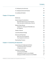
Your IP Phones and Accessories 24 Getting to Know Your WRV200 Router 26 Getting to Know the SLM224P Switch 28 Chapter 2: Installation and Configuration Process Overview 31 A. Preparation 31 B. Connecting the Equipment 31 SPA9000 Voice System Installation and Configuration Guide for Web - Linksys SPA921 | Cisco SPA9000 Voice System Web-UI Based Product Installation an - Page 4
Quality of Service 35 Network Setup Review 36 Infrastructure, Cabling and PSTN/ISDN Lines 36 NAT Mapping 37 Quality of Service 38 Local Area Network Design 38 Services and Equipment 39 Basic Services and Equipment 39 Cisco Equipment and Services 39 Downloading Firmware 40 Chapter - Linksys SPA921 | Cisco SPA9000 Voice System Web-UI Based Product Installation an - Page 5
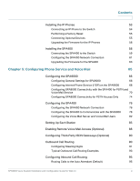
a Factory Reset 55 Connecting Optional Devices 55 Upgrading the Firmware for the IP Phones 56 Installing the SPA400 58 Connecting the SPA400 to the Switch 59 Configuring the SPA400 Network Connection 61 Upgrading the Firmware for the SPA400 63 Chapter 5: Configuring Phone Service and - Linksys SPA921 | Cisco SPA9000 Voice System Web-UI Based Product Installation an - Page 6
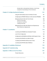
the SPA400 Call Disconnect Tones 129 Localizing the SPA400 Caller ID Method 131 Appendix A: Installation Workbook 133 Appendix B: Troubleshooting 148 Appendix C: Where to Go From Here Product Resources 157 157 SPA9000 Voice System Installation and Configuration Guide for Web UI iv - Linksys SPA921 | Cisco SPA9000 Voice System Web-UI Based Product Installation an - Page 7
Related Documentation Contents 158 SPA9000 Voice System Installation and Configuration Guide for Web UI v - Linksys SPA921 | Cisco SPA9000 Voice System Web-UI Based Product Installation an - Page 8
PBX, one or more SPA900 Series IP phones, and the optional SPA400 PSTN gateway and voice mail server. This guide focuses primarily on the tasks that an administrator performs to configure a SPA9000 with the SPA9000 administration web server. NOTE This guide does not cover initial installation and - Linksys SPA921 | Cisco SPA9000 Voice System Web-UI Based Product Installation an - Page 9
• System administrators or anyone who installs and manages the SPA9000 Voice System NOTE This guide does not provide the configuration information required by specific service providers. Please consult with the service provider for specific service parameters. Firmware This guide describes the - Linksys SPA921 | Cisco SPA9000 Voice System Web-UI Based Product Installation an - Page 10
" This chapter explains how to connect your equipment and upgrade the firmware. At the end of each section, you verify that the installation is progressing correctly. Chapter 5, "Configuring Phone Service and Voice Mail" This chapter guides you through the basic tasks that are required to get - Linksys SPA921 | Cisco SPA9000 Voice System Web-UI Based Product Installation an - Page 11
to be entered in a field. May indicate either of the following: • A variable that should be replaced with a literal value. • The name of a page, section, or field in the user interface Indicates code samples or system output. SPA9000 Voice System Installation and Configuration Guide for Web UI ix - Linksys SPA921 | Cisco SPA9000 Voice System Web-UI Based Product Installation an - Page 12
in a PDF file. STEP 1 Enter your search terms in the Find text box on the toolbar. NOTE By default, the Find tool is available at the right end of the Acrobat toolbar. If the Find tool does not more instances of the term. SPA9000 Voice System Installation and Configuration Guide for Web UI x - Linksys SPA921 | Cisco SPA9000 Voice System Web-UI Based Product Installation an - Page 13
you want to specify additional search criteria, click Use Advanced Search Options, and choose the options you want. d. Click Search. SPA9000 Voice System Installation and Configuration Guide for Web UI xi - Linksys SPA921 | Cisco SPA9000 Voice System Web-UI Based Product Installation an - Page 14
where the search terms appear. For more information about the Find and Search functions, see the Adobe Acrobat online help. SPA9000 Voice System Installation and Configuration Guide for Web UI xii - Linksys SPA921 | Cisco SPA9000 Voice System Web-UI Based Product Installation an - Page 15
System uses standard TCP/IP protocols and can provide global connectivity through any Internet Telephony Service Provider (ITSP) that supports the Session Initiation Protocol (SIP). At minimum, the SPA9000 Voice System includes a SPA9000 IP PBX and one or more SPA900 series IP phones. These devices - Linksys SPA921 | Cisco SPA9000 Voice System Web-UI Based Product Installation an - Page 16
each line interface. If a service provider supplies a group of sequential direct inward dial (DID) phone numbers (such as 408-555-0100 through 555-0145) the SPA9000 can support all of the assigned numbers on a single line interface. SPA9000 Voice System Installation and Configuration Guide for Web - Linksys SPA921 | Cisco SPA9000 Voice System Web-UI Based Product Installation an - Page 17
Series SIP IP Phones, as well as the Cisco WIP310 Wireless IP Phone. NOTE This guide explains how to configure the SPA9000 and the SPA400 to support the calling features on the phones. For more information about the phones, see the SPA9x2 Phone Administration Guide, the SPA9x2 Phone User Guide, and - Linksys SPA921 | Cisco SPA9000 Voice System Web-UI Based Product Installation an - Page 18
with four FXO ports, and another SPA400 for local voice mail service. Up to 16 IP phones can be installed. Optionally, analog phones or fax machines (not illustrated) can be connected to the two phone ports on the SPA9000. SPA9000 Voice System Installation and Configuration Guide for Web UI 16 - Linksys SPA921 | Cisco SPA9000 Voice System Web-UI Based Product Installation an - Page 19
SPA9000 Voice System is deployed with the SPA9000 IP PB and VoIP service. Up to 16 IP phones can be installed. Optionally, analog phones or fax machines (not illustrated) can be connected to the two phone ports on the SPA9000. SPA9000 Voice System Installation and Configuration Guide for Web UI 17 - Linksys SPA921 | Cisco SPA9000 Voice System Web-UI Based Product Installation an - Page 20
mail service, and another SPA400 unit for PSTN access with four FXO ports. Up to 16 IP phones can be installed. Optionally, analog phones or fax machines (not illustrated) can be connected to the two phone ports on the SPA9000. SPA9000 Voice System Installation and Configuration Guide for Web UI - Linksys SPA921 | Cisco SPA9000 Voice System Web-UI Based Product Installation an - Page 21
includes an ISDN Gateway for ISDN BRI access with four BRI ports. Up to 16 IP phones can be installed. Optionally, analog phones or fax machines (not illustrated) can be connected to the two phone ports on the SPA9000. SPA9000 Voice System Installation and Configuration Guide for Web UI 19 - Linksys SPA921 | Cisco SPA9000 Voice System Web-UI Based Product Installation an - Page 22
Your SPA400," on page 22 • "Getting to Know Your IP Phones and Accessories," on page 24 • "Getting to Know IP PBX system with high-end features comparable to traditional large business voice services. This section describes the LEDs on the front panel and the ports Configuration Guide for Web UI 20 - Linksys SPA921 | Cisco SPA9000 Voice System Web-UI Based Product Installation an - Page 23
hook. SPA9000 Back Panel Port PHONE 1, PHONE 2 ETHERNET INTERNET POWER Description/Notes Use these ports to connect analog phones or fax machines to your IP phone account. The use of this port is deprecated. You can use it for direct connection of an administration computer, but the recommended - Linksys SPA921 | Cisco SPA9000 Voice System Web-UI Based Product Installation an - Page 24
activity is occurring over the ETHERNET port. • Steady green: The line is active. • Flashing: The line is ringing. • Off: The line is idle. • Steady green: The USB voice mail module is registered. • Off: No module is detected. SPA9000 Voice System Installation and Configuration Guide for Web UI 22 - Linksys SPA921 | Cisco SPA9000 Voice System Web-UI Based Product Installation an - Page 25
Local Area Network (LAN) for communications with SPA9000. These FXO ports are used to connect to an analog phone lines. This button is used to reset the device. Use this port to connect to the external Power adapter (PA100). SPA9000 Voice System Installation and Configuration Guide for Web UI 23 - Linksys SPA921 | Cisco SPA9000 Voice System Web-UI Based Product Installation an - Page 26
(PoE) support SPA942* 2 4 Four-line IP phone with Power over Ethernet (PoE) support SPA962* WIP310 2 6 N/A 1 Six-line IP Phone with high-resolution color display and Power over Ethernet (PoE) support Wireless-G IP phone SPA9000 Voice System Installation and Configuration Guide for Web UI - Linksys SPA921 | Cisco SPA9000 Voice System Web-UI Based Product Installation an - Page 27
with 32 buttons and LEDs for monitoring and call transfer Provides an 802.3af PoE port for connection back to a PoE switch for SPA9000 and SPA400 Converts your IP phone into a wireless device, so it can connect to your wireless network without an Ethernet cable NOTE * SPA922/942/962 do not include - Linksys SPA921 | Cisco SPA9000 Voice System Web-UI Based Product Installation an - Page 28
or receiving data over the DMZ port. • Green: The router is connected to a Broadband Access device at the indicated speed (10, 100, 1000). • Flashing Green: The router is transmitting or receiving data over the INTERNET port. SPA9000 Voice System Installation and Configuration Guide for Web UI 26 - Linksys SPA921 | Cisco SPA9000 Voice System Web-UI Based Product Installation an - Page 29
four Ethernet ports. • Green: The Router is connected to a device through the corresponding port (1, 2, 3, or 4). • Flashing Green: The Router is actively sending or receiving data over the corresponding port. WRV200 Back Panel SPA9000 Voice System Installation and Configuration Guide for Web UI - Linksys SPA921 | Cisco SPA9000 Voice System Web-UI Based Product Installation an - Page 30
experiencing extreme problems with the router and have tried all other troubleshooting measures, press and hold in the Reset button for 10 seconds. This action restores the factory defaults and clears all of the Router's settings, such as port forwarding or a new password. Use this port to connect - Linksys SPA921 | Cisco SPA9000 Voice System Web-UI Based Product Installation an - Page 31
port with an attached device. • To reboot the switch, press and hold the Reset button for approximately five seconds. • To reset the Switch settings to the factory defaults, press and hold the Reset Button for approximately ten seconds. SPA9000 Voice System Installation and Configuration Guide - Linksys SPA921 | Cisco SPA9000 Voice System Web-UI Based Product Installation an - Page 32
) port is a connection point for a mini-GBIC expansion module, so the switch can be uplinked via fiber to another switch. SLM224P Back Panel The back panel has one port, the Power port, which is used to connect the power cord. SPA9000 Voice System Installation and Configuration Guide for Web UI - Linksys SPA921 | Cisco SPA9000 Voice System Web-UI Based Product Installation an - Page 33
and PSTN access. You also learn how to install the IP phones and any accessories such as PoE adapters and wall-mount brackets. You also upgrade the firmware with the new files that you downloaded during the Preparation phase. C. Configuring Voice Services After you connect the equipment, you need to - Linksys SPA921 | Cisco SPA9000 Voice System Web-UI Based Product Installation an - Page 34
console, and to route calls with hunt groups and shared line appearances. E. Localizing the System For customers outside North America, you need to localize the system. Chapter 7, "Localization," guides you through the steps. SPA9000 Voice System Installation and Configuration Guide for Web UI 32 - Linksys SPA921 | Cisco SPA9000 Voice System Web-UI Based Product Installation an - Page 35
premises or remotely over the phone and email. Various site survey templates can be used. Appendix A, "Installation Workbook," contains a site survey template example that you can use to record the customer information. SPA9000 Voice System Installation and Configuration Guide for Web UI 33 - Linksys SPA921 | Cisco SPA9000 Voice System Web-UI Based Product Installation an - Page 36
maximum number of simultaneous calls that the system can support with the appropriate audio quality. Before installing and configuring the Cisco SPA devices, use this information to determine the maximum number of simultaneous VoIP connections that the system can support. For asymmetric connections - Linksys SPA921 | Cisco SPA9000 Voice System Web-UI Based Product Installation an - Page 37
connection for voice services only. A separate connection is required when the broadband connection services do not offer quality of service and when it is not possible to apply the above mentioned utilization mechanism. SPA9000 Voice System Installation and Configuration Guide for Web UI 35 - Linksys SPA921 | Cisco SPA9000 Voice System Web-UI Based Product Installation an - Page 38
the Cisco SPA devices and by using the Power over Ethernet adapter (POES5) for the non-POE products (SPA9000, SPA400, SPA9x1 phones). Also ensure that devices such as the WAN modem, CSU/ DSU, or DDS modem are connected to the UPS. SPA9000 Voice System Installation and Configuration Guide for Web UI - Linksys SPA921 | Cisco SPA9000 Voice System Web-UI Based Product Installation an - Page 39
If this is the case, and if the external (public) IP address is static, then Cisco recommends mapping a static (permanent) IP address on the SPA9000. Instructions are available in the SPA9000 Voice System Administration Guide. • Configuring NAT Mapping with Simple Traversal of UDP through NAT (STUN - Linksys SPA921 | Cisco SPA9000 Voice System Web-UI Based Product Installation an - Page 40
IP phones may reboot on the event of an IP address change because of lease time expiration. • Use stable DNS server addresses for URL name resolution. Your Internet Service Provider can provide the primary and secondary DNS server IP addresses. SPA9000 Voice System Installation and Configuration - Linksys SPA921 | Cisco SPA9000 Voice System Web-UI Based Product Installation an - Page 41
, supporting a "bring your own device" model You must have at least the following information about your account: • SIP Proxy (IP address or name) • Account Information and Password • Computer with Microsoft Windows XP or Windows Vista (for system configuration) • Analog phone for administrative use - Linksys SPA921 | Cisco SPA9000 Voice System Web-UI Based Product Installation an - Page 42
, for providing Wireless client functionality to IP Phones, if required to connect a phone to the LAN using Wireless technology. Downloading Firmware Cisco recommends that you check for recent updates before you install your equipment. Later instructions in this guide will help you to install the - Linksys SPA921 | Cisco SPA9000 Voice System Web-UI Based Product Installation an - Page 43
how to connect your equipment and upgrade the firmware. At the end of each section, you verify that the installation is progressing correctly. • "Connecting and Configuring the Switch," on page 41 • "Installing the SPA9000," on page 46 • "Installing the IP Phones," on page 53 • "Installing the - Linksys SPA921 | Cisco SPA9000 Voice System Web-UI Based Product Installation an - Page 44
port on the switch. STEP 2 Connect an administrative computer to an Ethernet port on the switch. The PC needs to have an IP address on the same network as the switch, which has a default IP address to configure the switch. SPA9000 Voice System Installation and Configuration Guide for Web UI 42 - Linksys SPA921 | Cisco SPA9000 Voice System Web-UI Based Product Installation an - Page 45
ports that you will use to connect the SPA9000 and the IP phones. STEP 2 Connect the administration computer to the switch. STEP 3 Start Internet Explorer, and enter the IP address of the switch. The default IP address of the switch is 192.168.1.254. The default User ID is admin, with no password - Linksys SPA921 | Cisco SPA9000 Voice System Web-UI Based Product Installation an - Page 46
the Equipment Connecting and Configuring the Switch 4 STEP 7 From the Port Fast drop-down list, choose Enable. SLM224P Spanning Tree tab > STP Port Settings page STEP 8 Click Update. STEP 9 Repeat the previous steps to enable STP and Port Fast on each port where an IP phone or a SPA400 will be - Linksys SPA921 | Cisco SPA9000 Voice System Web-UI Based Product Installation an - Page 47
Connecting the Equipment Connecting and Configuring the Switch STEP 4 Click QoS tab > Basic Mode. 4 STEP 5 From the Trust Mode list, select DSCP. SLM224P QoS tab > Basic Mode page STEP 6 Click Save Settings. SPA9000 Voice System Installation and Configuration Guide for Web UI 45 - Linksys SPA921 | Cisco SPA9000 Voice System Web-UI Based Product Installation an - Page 48
switch, to administer it with an analog phone and a computer, to upgrade the firmware, and to set up the WAN connection. Upgrading the Firmware for the SPA9000," on page 48 • "Setting Up the WAN Connection for the SPA9000," on page 51 SPA9000 Voice System Installation and Configuration Guide for Web - Linksys SPA921 | Cisco SPA9000 Voice System Web-UI Based Product Installation an - Page 49
provide SPA9000 with Power over Ethernet support, you can connect/use POES5 Power over Ethernet adapter. • If the SPA9000 has been used previously, reset it to the factory defaults before you proceed to the other steps in the configuration process. See "To factory reset the SPA9000 (if needed)," on - Linksys SPA921 | Cisco SPA9000 Voice System Web-UI Based Product Installation an - Page 50
for factory reset: 73738# d. When prompted, press the code to confirm: 1# e. Wait about 30 seconds while the system reboots. Upgrading the Firmware for the SPA9000 In this procedure, you install any firmware updates that you downloaded in the Preparation phase. STEP 1 Use the IVR to check the IP - Linksys SPA921 | Cisco SPA9000 Voice System Web-UI Based Product Installation an - Page 51
4 c. In the next window that appears, enter the IP address of the SPA9000, and then click OK. d. In the Confirm Upgrade window, verify that the correct device information and product number appear. Then click Upgrade. SPA9000 Voice System Installation and Configuration Guide for Web UI 49 - Linksys SPA921 | Cisco SPA9000 Voice System Web-UI Based Product Installation an - Page 52
verify the upgrade, start Internet Explorer, and enter the IP address of the SPA9000. Check the Router >S tatus page. The Software Version field should show the firmware version that you installed. SPA9000 Router tab > Status page SPA9000 Voice System Installation and Configuration Guide for Web UI - Linksys SPA921 | Cisco SPA9000 Voice System Web-UI Based Product Installation an - Page 53
issues that would occur if the IP address of the SPA9000 changed. STEP 1 Start Internet Explorer, and enter the IP address of the SPA9000. The Router > Status page appears. By default, the page is in Basic User mode. STEP 2 Log on to the administrator view by clicking Admin Login, near the top right - Linksys SPA921 | Cisco SPA9000 Voice System Web-UI Based Product Installation an - Page 54
the SPA9000 4 STEP 6 In the Optional Settings area, enter the Primary DNS for your network. SPA9000 Router tab > Wan Setup page: Optional Settings section NOTE It is recommended to set an IP address that is outside the address range assigned by the DHCP server. For example, if the DHCP server - Linksys SPA921 | Cisco SPA9000 Voice System Web-UI Based Product Installation an - Page 55
the following topics: • "Connecting an IP Phone to the Switch," on page 54 • "Performing a Factory Reset," on page 55 • "Connecting Optional Devices," on page 55 • "Upgrading the Firmware for the IP Phones," on page 56 SPA9000 Voice System Installation and Configuration Guide for Web UI 53 - Linksys SPA921 | Cisco SPA9000 Voice System Web-UI Based Product Installation an - Page 56
Proxy is the IP address of the SPA9000. • Confirm that you can place an internal call from an IP phone by dialing a phone extension. NOTE You will learn how to configure your system for external calling later in this guide. SPA9000 Voice System Installation and Configuration Guide for Web UI 54 - Linksys SPA921 | Cisco SPA9000 Voice System Web-UI Based Product Installation an - Page 57
a Factory Reset If an IP phone has been used before, it may not register to the SPA9000 because it has the IP address and registration information from a previous SPA9000. To allow the auto-provisioning feature of the SPA9000 to configure your phone for you, reset it to the factory default settings - Linksys SPA921 | Cisco SPA9000 Voice System Web-UI Based Product Installation an - Page 58
file, and then run the executable file to upgrade the firmware. b. When the Firmware Upgrade Warning window appears, click Continue. c. In the next window that appears, enter the IP address of the phone, and then click OK. SPA9000 Voice System Installation and Configuration Guide for Web UI 56 - Linksys SPA921 | Cisco SPA9000 Voice System Web-UI Based Product Installation an - Page 59
that the correct device information and product number appear. Then click Upgrade. A progress message appears while the upgrade is in progress. The success window appears when the upgrade is completed. The device reboots. SPA9000 Voice System Installation and Configuration Guide for Web UI 57 - Linksys SPA921 | Cisco SPA9000 Voice System Web-UI Based Product Installation an - Page 60
of VoIP, PSTN and ISDN line/services), you can connect up to four SPA400 devices to your SPA9000 Voice System. This section includes the following topics: • "Connecting the SPA400 to the Switch," on page 59 • "Configuring the SPA400 Network Connection," on page 61 • "Upgrading the Firmware for - Linksys SPA921 | Cisco SPA9000 Voice System Web-UI Based Product Installation an - Page 61
. • If you install multiple SPA400 units, keep track of the MAC addresses to ensure that you know which device you are configuring. In the administration web server, you can see the MAC address by clicking the Status tab. SPA9000 Voice System Installation and Configuration Guide for Web UI 59 - Linksys SPA921 | Cisco SPA9000 Voice System Web-UI Based Product Installation an - Page 62
flashes and then shines steady green. The Status LED remains flashing until the SPA400 is registered to the SPA9000. NOTE You will learn how to configure the SPA400 in Chapter 5, "Configuring Phone Service and Voice Mail." SPA9000 Voice System Installation and Configuration Guide for Web UI 60 - Linksys SPA921 | Cisco SPA9000 Voice System Web-UI Based Product Installation an - Page 63
DHCP. You can check the obtained IP address on the router DHCP server's client list. • If your SPA400 has been used before or it is not reachable, factory reset the unit by pressing the Reset button for 10 seconds. STEP 2 When the password prompt appears, enter the default user name, Admin, with no - Linksys SPA921 | Cisco SPA9000 Voice System Web-UI Based Product Installation an - Page 64
.gov. • Time Zone: Select the time zone for your region. STEP 5 Click Save Settings. The SPA400 will reboot. To reconnect to the web administration server, enter the new IP address for the SPA400 in the browser Address bar. SPA9000 Voice System Installation and Configuration Guide for Web UI 62 - Linksys SPA921 | Cisco SPA9000 Voice System Web-UI Based Product Installation an - Page 65
, enter the default user name, Admin, with no password. Then click OK. NOTE The user name must be entered exactly as shown: Admin. For information about managing system access, refer to the Cisco SPA9000 Voice System Administration Guide. STEP 3 Click Administration tab > Firmware Upgrade. STEP - Linksys SPA921 | Cisco SPA9000 Voice System Web-UI Based Product Installation an - Page 66
have successfully upgraded the firmware. NOTE You may need to refresh your browser to display the updated banner reflecting the new version number. Congratulations, your SPA9000 Voice System is installed and ready for configuration. Proceed to Chapter 5, "Configuring Phone Service and Voice Mail - Linksys SPA921 | Cisco SPA9000 Voice System Web-UI Based Product Installation an - Page 67
5 Configuring Phone Service and Voice Mail This chapter guides you through the basic tasks that are required to get your voice system running. After you complete these procedures, users will be able to place and receive calls from the ITSP and from the PSTN. Callers will be able to leave voice mail, - Linksys SPA921 | Cisco SPA9000 Voice System Web-UI Based Product Installation an - Page 68
voice network. Complete this procedure before performing any other configuration tasks. STEP 1 Start Internet Explorer, and then enter the IP address of the SPA9000. Click Admin Login and then click Advanced. STEP 2 Click Voice tab > SIP. STEP 3 Enter the following settings: • Under PBX Parameters - Linksys SPA921 | Cisco SPA9000 Voice System Web-UI Based Product Installation an - Page 69
Configuring Phone Service and Voice Mail Configuring the SPA9000 5 • In the PBX Phone Parameters section, set CTI Enable to Yes. This setting supports special features such as Busy Lamp Field. SPA9000 Voice tab > SIP page: PBX Phone Parameters section • In the Auto Attendant Parameters section, - Linksys SPA921 | Cisco SPA9000 Voice System Web-UI Based Product Installation an - Page 70
for your ITSP account: • User ID: The account number or logon name for your ITSP account (often the same as the phone number) • Password: The password for your ITSP account • Proxy: The proxy server for your ITSP account SPA9000 Voice System Installation and Configuration Guide for Web UI 68 - Linksys SPA921 | Cisco SPA9000 Voice System Web-UI Based Product Installation an - Page 71
Configuring Phone Service and Voice Mail Configuring the SPA9000 Use the following illustration as a guide. SPA9000 Voice tab > Line 1 page 5 • SIP Port: You can keep the default value of 5060 for Line 1. Each line must have a unique SIP port. • Contact List: Leave the default value, aa, for the - Linksys SPA921 | Cisco SPA9000 Voice System Web-UI Based Product Installation an - Page 72
(PSTN). The SPA400 sets up and tears down calls between the PSTN and IP Phones offering seamless telephone service with Cisco VoIP equipment. To enable this service, you assign a User ID and port on the SPA400, and you configure the corresponding "Line" settings on the SPA9000. The SPA9000 Voice - Linksys SPA921 | Cisco SPA9000 Voice System Web-UI Based Product Installation an - Page 73
for ITSP service and Line 2 is used for the SPA400 interface. STEP 3 Enter the following information about the SPA400: • User ID: 9000 This ID corresponds to the User ID that you will enter on the SPA400 configuration page. The entries must match exactly. • Proxy: Enter the IP address of the SPA400 - Linksys SPA921 | Cisco SPA9000 Voice System Web-UI Based Product Installation an - Page 74
line must have a unique SIP port. • Contact List: Leave the default value, aa, for the Auto Attendant. Later, you can make changes. Using this basic setting at this point simplifies your testing and verification of the configuration. SPA9000 Voice System Installation and Configuration Guide for Web - Linksys SPA921 | Cisco SPA9000 Voice System Web-UI Based Product Installation an - Page 75
30 seconds, and prevents problems when you make changes in the settings. Use the following illustration as a guide. SPA9000 Voice tab > SIP page: Proxy and Registration section STEP 6 ****Click Submit All Changes. The SPA9000 device reboots. The SPA9000 is now configured to register the SPA400 - Linksys SPA921 | Cisco SPA9000 Voice System Web-UI Based Product Installation an - Page 76
3 Enter the following information about the SPA400: • User ID: 9000 This ID corresponds to the User ID that you entered on the SPA400 configuration page. They must match exactly. • Proxy: Enter the IP address of the SPA400. SPA9000 Voice System Installation and Configuration Guide for Web UI 74 - Linksys SPA921 | Cisco SPA9000 Voice System Web-UI Based Product Installation an - Page 77
every 60 seconds. This setting ensures that any future changes in settings are synchronized on both devices. Use the following illustration as a guide. SPA9000 Voice tab > SIP page STEP 4 Click Submit All Changes. SPA9000 Voice System Installation and Configuration Guide for Web UI 75 - Linksys SPA921 | Cisco SPA9000 Voice System Web-UI Based Product Installation an - Page 78
to obtain an IP Address via DHCP. You can check the obtained IP address on the router DHCP server's client list. STEP 2 When the password prompt appears, enter the default user name, Admin, with no password. Then click OK. SPA9000 Voice System Installation and Configuration Guide for Web UI 76 - Linksys SPA921 | Cisco SPA9000 Voice System Web-UI Based Product Installation an - Page 79
5 NOTE The user name must be entered exactly as shown: Admin. For information about managing system access, refer to the Cisco SPA9000 Voice System Administration Guide. STEP 3 Click Setup tab > Basic Setup. STEP 4 Enter the following settings: Network Setup section: • Fixed IP address: Click the - Linksys SPA921 | Cisco SPA9000 Voice System Web-UI Based Product Installation an - Page 80
Configuring Phone Service and Voice Mail Configuring the SPA400 SPA400 Setup tab > Basic Setup page 5 STEP 5 Click Save Settings. The SPA400 will reboot. To reconnect to the web administration server, enter the new IP address for the SPA400 in the browser Address bar. Configuring the SPA400 to - Linksys SPA921 | Cisco SPA9000 Voice System Web-UI Based Product Installation an - Page 81
the User ID that you entered on the corresponding SPA9000 Voice > Line page. • SPA9000 Address: Select the Discover Automatically radio button (required for SPA9000 operation). This setting enables the SPA400 to learn the IP address and the UDP port of the SPA9000 the from the SIP Registration - Linksys SPA921 | Cisco SPA9000 Voice System Web-UI Based Product Installation an - Page 82
Configuring Phone Service and Voice Mail Configuring the SPA400 Use the following illustration as a guide. SPA400 Setup tab > Voice page 5 STEP 6 Click Save Settings at the bottom of the page. STEP 7 To restart the SPA400, complete the following steps: a. Click Administration tab > Reboot. b. - Linksys SPA921 | Cisco SPA9000 Voice System Web-UI Based Product Installation an - Page 83
Configuring Phone Service and Voice Mail Configuring the SPA400 5 b. If you connected PSTN lines to the ports on the SPA400, confirm that you can place an external call to the phone number that is associated with the PSTN line. The Auto Attendant answers the call. You can then dial one of the - Linksys SPA921 | Cisco SPA9000 Voice System Web-UI Based Product Installation an - Page 84
corresponding settings in the phone configuration. NOTE This procedure is not required if you are using an external voice mail service. STEP 1 If your web browser is not already connected to the SPA400 web configuration utility, start Internet Explorer, and enter the IP address of the SPA400, and - Linksys SPA921 | Cisco SPA9000 Voice System Web-UI Based Product Installation an - Page 85
can change their own passwords after logging on with the assigned password. SPA400 Setup tab > Voicemail Users page NOTE Later you will set up the voice mail for each station. STEP 4 Click Save Settings at the bottom of the page. SPA9000 Voice System Installation and Configuration Guide for Web - Linksys SPA921 | Cisco SPA9000 Voice System Web-UI Based Product Installation an - Page 86
Configuring Phone Service and Voice Mail Configuring the SPA400 STEP 5 Restart the SPA400 by completing the following steps: a. Click Administration tab > Reboot. 5 b. Click Restart System. c. When the confirmation message appears, click OK. The SPA400 reboots. d. When the Reboot OK. Go to Setup - Linksys SPA921 | Cisco SPA9000 Voice System Web-UI Based Product Installation an - Page 87
the hyperlink in the IP Address column. The Telephone Configuration page appears in a separate browser window. STEP 4 To enter a station name for the phone (recommended), complete the following tasks: a. Click the Phone tab. SPA9000 Voice System Installation and Configuration Guide for Web UI 85 - Linksys SPA921 | Cisco SPA9000 Voice System Web-UI Based Product Installation an - Page 88
section NOTE This setting assists you in managing the phones. STEP 5 To configure voice mail service with the SPA400 voice mail server, complete the following tasks: a. Click the Ext 1 tab. b. Under Call Feature Settings, enter the Mailbox ID in the following format: Example: 2105 - Linksys SPA921 | Cisco SPA9000 Voice System Web-UI Based Product Installation an - Page 89
the mailbox. • "Mailbox number" prompt: This prompt indicates that no mailbox is assigned to this station. Review the settings on the SPA400 Setup tab > Voicemail User page (see "Configuring the Voice Mail Server and Voice SPA9000 Voice System Installation and Configuration Guide for Web UI 87 - Linksys SPA921 | Cisco SPA9000 Voice System Web-UI Based Product Installation an - Page 90
, your ITSP must support out-of-band DTMF. STEP 1 Start Internet Explorer, and then enter the IP address of the SPA9000. Click Admin Login and then click Advanced. STEP 2 Click Voice > SIP. STEP 3 Scroll down to the Auto Attendant Parameters section. STEP 4 Edit the AA Dial Plan 1 string to include - Linksys SPA921 | Cisco SPA9000 Voice System Web-UI Based Product Installation an - Page 91
: Replace N with the number of the SPA9000 line interface (Line 1 ... Line 4) that is configured for the SPA400 voice mail server. SPA9000 Voice tab > SIP page: Auto Attendant Parameters section STEP 5 Copy and paste the same string into the AA Dial Plan 2 field, for the purpose of allowing remote - Linksys SPA921 | Cisco SPA9000 Voice System Web-UI Based Product Installation an - Page 92
Examples," on page 93 • "Routing Calls to the Auto Attendant (Default)," on page 95 • "Routing Calls to a Receptionist, Extension, or Hunt Group," on page 96 • "Using Direct Inward Dialing to Phone Extensions," on page 98 SPA9000 Voice System Installation and Configuration Guide for Web UI 90 - Linksys SPA921 | Cisco SPA9000 Voice System Web-UI Based Product Installation an - Page 93
Configuring Phone Service and Voice Mail Outbound Call Routing 5 Configuring Steering Digits Follow this procedure to configure the steering digits. STEP 1 Start Internet Explorer, and then enter the IP address of the SPA9000. Click Admin Login and then click Advanced. STEP 2 Click Voice tab > SIP - Linksys SPA921 | Cisco SPA9000 Voice System Web-UI Based Product Installation an - Page 94
same steering digit that you configured for L1 in the Call Routing Rule. NOTE In case you are using a Line (2, 3, 4) for backup of Line 1, you need to include in the backup Line dial plan, the entry of the Line 1 dial plan. SPA9000 Voice System Installation and Configuration Guide for Web UI 92 - Linksys SPA921 | Cisco SPA9000 Voice System Web-UI Based Product Installation an - Page 95
can accomplish various call routing goals by editing the call routing rule and the dial plans. • ITSP Only: Line 1 is configured for ITSP service. The user (in USA) would like to press 9 to dial outbound (default configuration). • Call Routing Rule: (9xx.) • Phone dial plan (US): (9,[3469]11S0 - Linksys SPA921 | Cisco SPA9000 Voice System Web-UI Based Product Installation an - Page 96
5 • ITSP and PSTN Service: Line 1 is configured for ITSP service and Line 2 for a SPA400 connected to PSTN service. The user (in USA) would like to press 9 for Line 1 and to press 8 for Line 2 to make outbound calls. • Call Routing Rule: (9xx. | 8xx.) • Phone dial plan (US): ([89],[3469 - Linksys SPA921 | Cisco SPA9000 Voice System Web-UI Based Product Installation an - Page 97
to the Auto Attendant (Default) By default, all incoming calls are routed to the Auto Attendant, where users are prompted to enter the extension number of the destination phone. STEP 1 Start Internet Explorer, and then enter the IP address of the SPA9000. Click Admin Login and then click Advanced - Linksys SPA921 | Cisco SPA9000 Voice System Web-UI Based Product Installation an - Page 98
Administration Guide. Routing Calls to a Receptionist, Extension, or Hunt Group The SPA9000 Voice System is able to route incoming call to any extension, including the receptionist phone, defined in the system. STEP 1 Start Internet Explorer, and then enter the IP address of the SPA9000. Click Admin - Linksys SPA921 | Cisco SPA9000 Voice System Web-UI Based Product Installation an - Page 99
, the incoming call is forwarded to the Auto Attendant. • Contact list: 100,cfwd=aa • Cfwd No Ans Delay: 15 STEP 5 Repeat this procedure for all active lines. STEP 6 Click Submit All Changes. The SPA9000 and the phones reboot. SPA9000 Voice System Installation and Configuration Guide for Web UI 97 - Linksys SPA921 | Cisco SPA9000 Voice System Web-UI Based Product Installation an - Page 100
and call routing: • + The extension will be alerted when there is an incoming call to the DID number, and the DID number will be used as the local user-ID in outbound SIP requests, along with the display-name of the extension. SPA9000 Voice System Installation and Configuration Guide for Web - Linksys SPA921 | Cisco SPA9000 Voice System Web-UI Based Product Installation an - Page 101
Configuring Phone Service and Voice Mail Configuring Inbound Call Routing 5 • - The extension will not be alerted when there is an incoming call to the DID number. However, the DID number will be used as the local user-ID in outbound SIP requests, along with the display-name of the - Linksys SPA921 | Cisco SPA9000 Voice System Web-UI Based Product Installation an - Page 102
Configuring Phone Service and Voice Mail Configuring Inbound Call Routing 5 STEP 2 Start Internet Explorer, and enter the IP address of the SPA9000. STEP 3 Click Admin Login, and then click Advanced. STEP 4 Click Voice tab > Line 1. STEP 5 Configure the Contact List parameter as described earlier - Linksys SPA921 | Cisco SPA9000 Voice System Web-UI Based Product Installation an - Page 103
. The SPA9000 ships with a default music file (Romance de Amor). Follow this procedure to enable the internal music source. NOTE For other Music On Hold options, see the Cisco SPA9000 Voice System Administration Guide. SPA9000 Voice System Installation and Configuration Guide for Web UI 101 - Linksys SPA921 | Cisco SPA9000 Voice System Web-UI Based Product Installation an - Page 104
call to the extension. When the call is answered and put on hold, the caller should hear the default music file (Romance de Amor). STEP 8 Repeat as needed for each extension on the phone, and for each phone that needs music on hold. SPA9000 Voice System Installation and Configuration Guide for Web - Linksys SPA921 | Cisco SPA9000 Voice System Web-UI Based Product Installation an - Page 105
Settings" on page_45. • SPA901, SPA921, SPA941 cannot be monitored for Busy Lamp Function (BLF) by the SPA962/SPA932, as these phones do not support CTI. • Each station can be monitored only by one SPA962/932 at a time. SPA9000 Voice System Installation and Configuration Guide for Web UI 103 - Linksys SPA921 | Cisco SPA9000 Voice System Web-UI Based Product Installation an - Page 106
the attachment arm to the SPA962. d. Using the other attachment arm screw, secure the attachment arm to the SPA932. e. Locate the AUX IN port on the back of the SPA932. Connect one end of the auxiliary cable to this port. SPA9000 Voice System Installation and Configuration Guide for Web UI 104 - Linksys SPA921 | Cisco SPA9000 Voice System Web-UI Based Product Installation an - Page 107
port of the SPA962 to a port on your switch. The display flickers briefly and then the color display appears with the assigned extension number. STEP 3 Use the administration computer to install the latest firmware for the SPA962. SPA9000 Voice System Installation and Configuration Guide for Web - Linksys SPA921 | Cisco SPA9000 Voice System Web-UI Based Product Installation an - Page 108
Status, near the top right corner of the web page. The screen lists each phone by station name and extension number. STEP 6 Find the User ID for the SPA962, and then click the hyperlink in the IP Address column. The Telephone Configuration page appears in a separate browser window. STEP 7 Click - Linksys SPA921 | Cisco SPA9000 Voice System Web-UI Based Product Installation an - Page 109
works only with SPA9x2 series phones, when CTI is enabled. SPA9x1 series phones do not support CTI. • sd: Speed Dial Allows the user to dial the selected extension quickly, either to place an internal call or to perform a blind transfer of an active call. • cp: Call Pickup (in combination with BLF - Linksys SPA921 | Cisco SPA9000 Voice System Web-UI Based Product Installation an - Page 110
of the device and the IP address of the SPA9000 NOTE The station name must exactly match the name that is entered in the phone configuration web page. The assigned names are displayed on the PBX Status page (click the PBX Status link on the main administration web page). For more information about - Linksys SPA921 | Cisco SPA9000 Voice System Web-UI Based Product Installation an - Page 111
both in the Contact List and on the SIP page > PBX Parameters section, the call forward parameter from the Contact List is ignored; instead, the call forward parameter defined on the SIP page > PBX Parameter section is used. SPA9000 Voice System Installation and Configuration Guide for Web UI 109 - Linksys SPA921 | Cisco SPA9000 Voice System Web-UI Based Product Installation an - Page 112
Configuring Special Features Managing Inbound Calls with Hunt Groups 6 Syntax for Hunt Rules • Global Hunt Rule (SIP page > PBX Parameters section > Hunt Groups field) SYNTAX: extension:[name="name",]station[,station[,station [...]]],hunt=hrule[,cfwd=target] • Line-Specific Hunt Rule (Line N page - Linksys SPA921 | Cisco SPA9000 Voice System Web-UI Based Product Installation an - Page 113
rule, this hunt group is assigned an extension number (500) and is given a name, Sales. For both examples, the rule includes three stations (101,102,103). An incoming call rings all three stations simultaneously (hunt=al). SPA9000 Voice System Installation and Configuration Guide for Web UI 111 - Linksys SPA921 | Cisco SPA9000 Voice System Web-UI Based Product Installation an - Page 114
in random order. Each phone rings for 30 seconds (30). After 1 cycle is completed, an unanswered call is forwarded to the voice mail for station 100, where Line 2 is configured for the voice mail service (1,cfwd=vm2100). SPA9000 Voice System Installation and Configuration Guide for Web UI 112 - Linksys SPA921 | Cisco SPA9000 Voice System Web-UI Based Product Installation an - Page 115
All Changes. The phones reboot. STEP 5 To verify the settings: • Global Rule: Place a call to the new hunt group by entering the extension number or by using the Corporate Directory to select the group name and dial the group. SPA9000 Voice System Installation and Configuration Guide for Web UI - Linksys SPA921 | Cisco SPA9000 Voice System Web-UI Based Product Installation an - Page 116
Groups 6 • Line-Specific Rule: From an external phone, such as a cellular phone, place a call to the phone number that is associated with the line interface. Verify that the call is routed according to the specified settings. SPA9000 Voice System Installation and Configuration Guide for Web UI - Linksys SPA921 | Cisco SPA9000 Voice System Web-UI Based Product Installation an - Page 117
station. • Flashing Red Slowly: A call is on hold. • Solid Red: A call is active on this station. • All stations with a display can monitor the status of any SLA that is configured. The icon next to the line key will change to show ringing, off-hook, or busy "" until the phone is back on-hook - Linksys SPA921 | Cisco SPA9000 Voice System Web-UI Based Product Installation an - Page 118
the phone display and in the Corporate Directory. SPA9xx Telephone Configuration > Ext: Shared Line Appearance c. Scroll down to the Subscriber Information section, and then enter a User ID and Display Name for this shared extension. SPA9000 Voice System Installation and Configuration Guide for Web - Linksys SPA921 | Cisco SPA9000 Voice System Web-UI Based Product Installation an - Page 119
- Short Name: Type the extension number that you entered as the Shared User ID for the extension. This extension number will appear on the phone display and in the Corporate Directory. SPA9xx Telephone Configuration: Ext: Line Key SPA9000 Voice System Installation and Configuration Guide for Web UI - Linksys SPA921 | Cisco SPA9000 Voice System Web-UI Based Product Installation an - Page 120
Inbound Calls with Shared Line Appearances 6 STEP 5 If needed, configure additional line keys for the same SLA. STEP 6 Click Submit All Changes. STEP 7 Repeat this procedure for each phone that you want to configure with the SLA. SPA9000 Voice System Installation and Configuration Guide for Web - Linksys SPA921 | Cisco SPA9000 Voice System Web-UI Based Product Installation an - Page 121
the SPA400 Caller ID Method," on page131 NOTE For instructions about localizing the phone display, see the SPA9x2 Phone Administration Guide. Localizing the SPA9000 Auto Attendant Prompts The default Auto Attendant prompts are in English. You can localize your system by downloading and installing - Linksys SPA921 | Cisco SPA9000 Voice System Web-UI Based Product Installation an - Page 122
/HTTP/HTTPS server. STEP 3 To configure the SPA9000 to download the files from the server, complete the following tasks: a. Start Internet Explorer, and then enter the IP address of the SPA9000. Click Admin Login and then click Advanced. b. Click Voice tab > the SIP tab. c. Scroll down to the - Linksys SPA921 | Cisco SPA9000 Voice System Web-UI Based Product Installation an - Page 123
, make a call to the Auto Attendant. From an internal phone, you can press the Setup button, then press 1 - Directory, then 2 Corporate Directory, and then scroll down to find and select the number for the Auto Attendant. SPA9000 Voice System Installation and Configuration Guide for Web UI 121 - Linksys SPA921 | Cisco SPA9000 Voice System Web-UI Based Product Installation an - Page 124
IP address of the SPA9000. Click Admin Login and then click Advanced. b. Click Voice tab > Regional. c. In the Call Progress Tones section, enter the values from Table 3-1 into the corresponding fields. d. Click Submit All Changes. SPA9000 Voice System Installation and Configuration Guide for Web - Linksys SPA921 | Cisco SPA9000 Voice System Web-UI Based Product Installation an - Page 125
phone that you want to configure, and then click the hyperlink in the IP Address column. c. Click Regional. d. In the Call Progress Tones section, enter the values from Table 2, 'SPA9000 Call Progress Tones by Country," on page123. e. Click Submit All Changes and Configuration Guide for Web UI 123 - Linksys SPA921 | Cisco SPA9000 Voice System Web-UI Based Product Installation an - Page 126
Localization Configuring the SPA9000 and SPA9xx Call Progress Tones 7 Ring Back Tone Busy Tone Call Waiting Tone Confirm Tone France Dial Tone Outside Dial Tone Prompt Tone Reorder Tone Off Hook Warning Tone Ring Back Tone Busy Tone Call Waiting Tone Confirm Tone Germany Dial Tone Outside Dial - Linksys SPA921 | Cisco SPA9000 Voice System Web-UI Based Product Installation an - Page 127
Localization Configuring the SPA9000 and SPA9xx Call Progress Tones 7 Prompt Tone Reorder Tone Off Hook Warning Tone Ring Back Tone Busy Tone Call Waiting Tone Confirm Tone Italy Dial Tone Outside Dial Tone Prompt Tone Reorder Tone Off Hook Warning Tone Ring Back Tone Busy Tone Call Waiting Tone - Linksys SPA921 | Cisco SPA9000 Voice System Web-UI Based Product Installation an - Page 128
Configuring the SPA9000 and SPA9xx Call Progress Tones Norway Dial Tone Outside Dial Tone Prompt Tone Reorder Tone Off Hook Warning Tone Ring Back Tone Busy Tone Call Waiting Tone Confirm Tone Portugal Dial Tone Outside Dial SPA9000 Voice System Installation and Configuration Guide for Web UI 7 126 - Linksys SPA921 | Cisco SPA9000 Voice System Web-UI Based Product Installation an - Page 129
Configuring the SPA9000 and SPA9xx Call Progress Tones 7 Busy Tone Call Waiting Tone Confirm Tone Sweden Dial Tone Outside Dial Tone Prompt Tone Reorder Tone Off Hook Warning Tone Ring Back Tone Busy Tone Call Waiting Tone Confirm Tone UK Dial Tone Outside Dial Configuration Guide for Web UI 127 - Linksys SPA921 | Cisco SPA9000 Voice System Web-UI Based Product Installation an - Page 130
default, the voice mail system is configured for the English language. You can localize the system by downloading and installing the appropriate language files for your region. STEP 1 Download the necessary language files from Cisco names check a USB port on the Configuration Guide for Web UI 128 - Linksys SPA921 | Cisco SPA9000 Voice System Web-UI Based Product Installation an - Page 131
has been terminated on the other end, so the local line hangs up automatically. Detecting the tone cadence of the Call Disconnect signal is a trigger for closing the loop. Each country has its own Call Disconnect Signal tone which needs to be configured on the SPA400 Tone page. See Table 3, 'SPA400 - Linksys SPA921 | Cisco SPA9000 Voice System Web-UI Based Product Installation an - Page 132
the SPA400 Call Disconnect Tones IP address of the SPA400, and log on. STEP 2 Click the Tone tab. SPA400 Tone page STEP 3 Enter the appropriate settings for your country, as listed in Table 3, 'SPA400 Call Processing Tones. SPA9000 Voice System Installation and Configuration Guide for Web - Linksys SPA921 | Cisco SPA9000 Voice System Web-UI Based Product Installation an - Page 133
caller ID method to use in your country. STEP 1 Click Setup tab > Voice. STEP 2 Scroll down to the Line Settings section. STEP 3 From the Caller Id and CP Tone Method drop-down list, choose your region. SPA400 Setup tab > Voice page SPA9000 Voice System Installation and Configuration Guide for Web - Linksys SPA921 | Cisco SPA9000 Voice System Web-UI Based Product Installation an - Page 134
, make a call from outside to any of the PSTN lines connected to the SPA400 (make sure that CID is enable in your PSTN line). In the ringing SPA phone display you should now be able to see the number from the calling number. SPA9000 Voice System Installation and Configuration Guide for Web UI 132 - Linksys SPA921 | Cisco SPA9000 Voice System Web-UI Based Product Installation an - Page 135
Contact Phone Number - Commercial Contact Email Address - Commercial Alternate Contact Phone Number Contact Name - IT Responsible Contact Phone Number - IT Responsible Contact email address - IT Responsible Installation Location SPA9000 Voice System Installation and Configuration Guide for Web UI - Linksys SPA921 | Cisco SPA9000 Voice System Web-UI Based Product Installation an - Page 136
this page as needed. You can configure the four SPA9000 interfaces with different service providers. Service Provider Name Service Provider Contact Information Service Order Number Service Activation Date Service Order Type SPA9000 Voice System Installation and Configuration Guide for Web UI 134 - Linksys SPA921 | Cisco SPA9000 Voice System Web-UI Based Product Installation an - Page 137
Installation Workbook Provisioning Information SIP Proxy User Name Password Provisioning Method (Circle one.) SPA9000 VOICE SYSTEM WIZARD VERSION WEB UI REMOTE PROVISIONING Service provider additional parameters (e.g. DID numbers) A Audio preferred codec (Circle one.) G.711A G.711u G.729a G.726 - Linksys SPA921 | Cisco SPA9000 Voice System Web-UI Based Product Installation an - Page 138
provided by the system Is the customer setup requiring any of the following features? (Circle all that apply.) Receptionist telephone Automatic attendant Direct Inward Dialing Voice mail Other (please specify): A SPA9000 Voice System Installation and Configuration Guide for Web UI 136 - Linksys SPA921 | Cisco SPA9000 Voice System Web-UI Based Product Installation an - Page 139
available for each YES / NO Cisco SPA device location (Circle one.) If no, where are the missing locations? PSTN Line (Circle one.) If yes, how many? YES / NO ISDN BRI Line (Circle one.) If yes, how the fax machine? SPA9000 Voice System Installation and Configuration Guide for Web UI A 137 - Linksys SPA921 | Cisco SPA9000 Voice System Web-UI Based Product Installation an - Page 140
specify: IP addressing type (Circle one.) DYNAMIC / STATIC If static, IP address If static, network mask Primary DNS Secondary DNS Bandwidth Uplink bandwidth requirement (including Internet access and VoIP) calculation SPA9000 Voice System Installation and Configuration Guide for Web UI 138 - Linksys SPA921 | Cisco SPA9000 Voice System Web-UI Based Product Installation an - Page 141
ID If yes, Data VLAN ID Power over Ethernet YES / NO If yes, how many ports available Total number of ports on switch WiFi Network (Circle one.) If yes, SSID YES / NO If yes, encryption type (Circle one.) WEP / WPA / WPA2 SPA9000 Voice System Installation and Configuration Guide for Web - Linksys SPA921 | Cisco SPA9000 Voice System Web-UI Based Product Installation an - Page 142
YES / NO Port Number: YES / NO YES / NO SPA400 - 1 YES / NO SPA400 - 2 YES / NO SPA400 - 3 YES / NO SPA400 - 4 YES / NO IP Phone 1 YES / NO IP Phone 2 YES / NO IP Phone 3 YES / NO IP Phone 4 YES / NO SPA9000 Voice System Installation and Configuration Guide for Web UI A 140 - Linksys SPA921 | Cisco SPA9000 Voice System Web-UI Based Product Installation an - Page 143
Installation Workbook IP Phone 5 IP Phone 6 IP Phone 7 IP Phone 8 IP Phone 9 IP Phone 10 IP Phone 11 IP Phone 12 IP Phone 13 IP Phone 14 IP Phone 15 IP Phone 16 Component Component Component Component YES / NO YES / NO SPA9000 Voice System Installation and Configuration Guide for Web UI A 141 - Linksys SPA921 | Cisco SPA9000 Voice System Web-UI Based Product Installation an - Page 144
/ NO YES / NO Cisco SPA devices SPA9000 Firmware version SPA901 Number of phones Firmware version SPA921 Number of phones Firmware version SPA941 Number of phones Firmware version SPA922 Number of phones Firmware version SPA9000 Voice System Installation and Configuration Guide for Web UI A 142 - Linksys SPA921 | Cisco SPA9000 Voice System Web-UI Based Product Installation an - Page 145
SPA932 Number of consoles SPA400 Number of gateways Firmware version POES5 Number of units WBP54G Number of units MB100 Number of units SPA9000 Voice System Configuration SPA9000 MAC ID Key Upgrade (opt) VM NOTES: SPA9000 Voice System Installation and Configuration Guide for Web UI A 143 - Linksys SPA921 | Cisco SPA9000 Voice System Web-UI Based Product Installation an - Page 146
Installation Workbook SPA400 #1 MAC ID NOTES: SPA400 #2 MAC ID NOTES: SPA400 #3 MAC ID NOTES: SPA400 #4 MAC ID NOTES: PSTN Phone Numbers VM PSTN Phone Numbers VM PSTN Phone Numbers VM PSTN Phone Numbers VM A SPA9000 Voice System Installation and Configuration Guide for Web UI 144 - Linksys SPA921 | Cisco SPA9000 Voice System Web-UI Based Product Installation an - Page 147
(enter station number) Copy and print this page as needed for each phone. Link Phone Model MAC ID DID Numbers WiFi / POE A L1 EXT Share / Private Hunt Group Voice Mail L2 EXT Share Hunt Group Voice Mail SPA9000 Voice System Installation and Configuration Guide for Web UI 145 - Linksys SPA921 | Cisco SPA9000 Voice System Web-UI Based Product Installation an - Page 148
Installation Workbook Additional Equipment Equipment Type Model MAC Address Notes Equipment Type Model MAC Address Notes Equipment Type Model MAC Address Notes Equipment Type Model MAC Address Notes SPA9000 Voice System Installation and Configuration Guide for Web UI A 146 - Linksys SPA921 | Cisco SPA9000 Voice System Web-UI Based Product Installation an - Page 149
Installation Workbook Additional Installation and Configuration Notes A SPA9000 Voice System Installation and Configuration Guide for Web UI 147 - Linksys SPA921 | Cisco SPA9000 Voice System Web-UI Based Product Installation an - Page 150
an extension number to the Cisco SPA IP Phone, and the phone Ext LED is yellow instead of green. A. The yellow LED indicates that the phone and the SPA9000 are not in communication with each other, possibly due to an IP address change or physical network problems. As a test, reboot the SPA9000 - Linksys SPA921 | Cisco SPA9000 Voice System Web-UI Based Product Installation an - Page 151
Troubleshooting B NOTE Alternatively, connect to the SPA9000 administration web server. Go to Voice > SIP page, PBX Parameters section, and find the address in the Multicast Address field. 2. Check the multicast address settings on the phone: - SPA901: Lift the receiver, and press **** to access - Linksys SPA921 | Cisco SPA9000 Voice System Web-UI Based Product Installation an - Page 152
not assigned to the phone. Review the settings on the SPA400 Voice mail User page to determine which mailboxes are configured. Next, check the Telephone Configuration > Ext 1 page, Call Feature Settings section. Make sure that the Mailbox ID field displays the correct line interface number for the - Linksys SPA921 | Cisco SPA9000 Voice System Web-UI Based Product Installation an - Page 153
is Registered. e. If the line interface is not registered, then click the Line N tab and enter the correct User ID, Proxy, and Password supplied by your Internet Telephony Service Provider (ITSP). f. Click Submit All Changes. SPA9000 Voice System Installation and Configuration Guide for Web UI 151 - Linksys SPA921 | Cisco SPA9000 Voice System Web-UI Based Product Installation an - Page 154
resolving the problem. For a brief overview, see "NAT Mapping," on page 37. For instructions, see the Cisco SPA9000 Voice System Administration Guide. Q. When an outside line calls the SPA9000, it rings one time and then goes to the Auto Attendant. A. By default, if no one answers the call after 12 - Linksys SPA921 | Cisco SPA9000 Voice System Web-UI Based Product Installation an - Page 155
behavior indicates that the dialed digits are not accepted by the dial plan. The Cisco SPA9000 Voice System Administration Guide includes instructions for modifying the default dial plan to accommodate various dialing scenarios. To better understand the problem, try dialing the number again, but - Linksys SPA921 | Cisco SPA9000 Voice System Web-UI Based Product Installation an - Page 156
a connectivity issue, and you need to troubleshoot the network environment. If the phone does reboot, then double-check the dial plan. Q. I want to use a different computer to access the administration web server. I entered http://SPA9000_ipaddress, but this address did not work. A. Investigate the - Linksys SPA921 | Cisco SPA9000 Voice System Web-UI Based Product Installation an - Page 157
Phone port on the SPA9000. b. Press the star (*) key four times: **** c. Press 7932#. d. Press 1# to enable WAN access to the administration web server. e. Press 1 to save the setting. • The SPA900 may be unavailable. a. Try pinging the IP address of the SPA9000. b. If you don't get a reply, check - Linksys SPA921 | Cisco SPA9000 Voice System Web-UI Based Product Installation an - Page 158
enter the IP address of the SPA9000. Click Admin Login and then click Advanced. b. From the menu, choose File > Save As. c. Save the configuration as Web Page Complete. You can use the saved file to review the saved settings in all pages of the administrative GUI. • SPA900 Series Phones: a. Start - Linksys SPA921 | Cisco SPA9000 Voice System Web-UI Based Product Installation an - Page 159
.com/community/ smallbizsupport/voiceandconferencing/voice Phone Support www.cisco.com/en/US/support/ tsd_cisco_small_business_support_center_contacts.html Warranty and End- www.cisco.com/go/warranty User License Agreement SPA9000 Voice System Installation and Configuration Guide for Web UI 157 - Linksys SPA921 | Cisco SPA9000 Voice System Web-UI Based Product Installation an - Page 160
Guide Web-UI (Legacy) Based Product Configuration Manual installation of the SPA9000 Voice System, by using the Web User Interface, instead of the Cisco SPA900 Voice System Setup Wizard. End Users, VARs, and Service Providers SPA9000 Voice System Installation and Configuration Guide for Web - Linksys SPA921 | Cisco SPA9000 Voice System Web-UI Based Product Installation an - Page 161
IP phones • Administration and use of Cisco Small Business ATAs • PAP2T, SPA2102, SPA3102, SPA8000, WRP400, and WRTP54G Intended Audience VARs and Service Providers VARs and Service Providers VARs and phone endusers VARs, system administrators, and Service Providers User Guide for switch User
-
 1
1 -
 2
2 -
 3
3 -
 4
4 -
 5
5 -
 6
6 -
 7
7 -
8
-
9
-
10
-
11
-
12
-
13
-
14
-
15
-
16
-
17
-
18
-
19
-
20
-
21
-
22
-
23
-
24
-
25
-
26
-
27
-
28
-
29
-
30
-
31
-
32
-
33
-
34
-
35
-
36
-
37
-
38
-
39
-
40
-
41
-
42
-
43
-
44
-
45
-
46
-
47
-
48
-
49
-
50
-
51
-
52
-
53
-
54
-
55
-
56
-
57
-
58
-
59
-
60
-
61
-
62
-
63
-
64
-
65
-
66
-
67
-
68
-
69
-
70
-
71
-
72
-
73
-
74
-
75
-
76
-
77
-
78
-
79
-
80
-
81
-
82
-
83
-
84
-
85
-
86
-
87
-
88
-
89
-
90
-
91
-
92
-
93
-
94
-
95
-
96
-
97
-
98
-
99
-
100
-
101
-
102
-
103
-
104
-
105
-
106
-
107
-
108
-
109
-
110
-
111
-
112
-
113
-
114
-
115
-
116
-
117
-
118
-
119
-
120
-
121
-
122
-
123
-
124
-
125
-
126
-
127
-
128
-
129
-
130
-
131
-
132
-
133
-
134
-
135
-
136
-
137
-
138
-
139
-
140
-
141
-
142
-
143
-
144
-
145
-
146
-
147
-
148
-
149
-
150
-
151
-
152
-
153
-
154
-
155
-
156
-
157
-
158
-
159
-
160
-
161
 |
 |
Cisco Small Business Pro
SPA9000 Voice System Version 6.1
Web-UI (Legacy) Based Product Configuration
INSTALLATION AND
CONFIGURATION
GUIDE