MSI K8T800 User Guide
MSI K8T800 - K8T Neo-FSR Motherboard Manual
 |
UPC - 816909005066
View all MSI K8T800 manuals
Add to My Manuals
Save this manual to your list of manuals |
MSI K8T800 manual content summary:
- MSI K8T800 | User Guide - Page 1
K8T Neo MS-6702 (v1.X) ATX Mainboard Version 1.1 G52-M6702X7 i - MSI K8T800 | User Guide - Page 2
compliance could void the user's authority to operate the equipment. Notice 2 Shielded interface cables and A.C. power cord, if any, must be used in order to comply with the emission limits. VOIR LA NOTICE D'INSTALLATION AVANT DE RACCORDER AU RESEAU. Micro-Star International MS-6702 Tested to comply - MSI K8T800 | User Guide - Page 3
If a problem arises with your system and no solution can be obtained from the user's manual, please contact your place of purchase or local distributor. Alternatively, please try the following help resources for further guidance. Visit the MSI website for FAQ, technical guide, BIOS updates, driver - MSI K8T800 | User Guide - Page 4
1. Always read the safety instructions carefully. 2. Keep this User's Manual for future reference. 3. Keep this equipment away shock. 11. If any of the following situations arises, get the equipment checked by a service personnel: z The power cord or plug is damaged. z Liquid has penetrated into the - MSI K8T800 | User Guide - Page 5
History iii Technical Support iii Safety Instructions v Chapter 1. Getting Started 1-1 Mainboard Specifications 1-2 Mainboard Layout 1-4 MSI Special Features 1-5 Color Management 1-5 Core Center 1-6 Core Cell™ Chip 1-9 Dynamic Overclocking Technology 1-10 Live BIOS™/Live Driver 1-11 Live - MSI K8T800 | User Guide - Page 6
,SER2 2-22 Serial ATA/Serial ATA RAID Connectors controlled by Promise 20378: SATA1, SATA2 2-22 Front Panel Audio Connectors: JAUD1 2-24 D-Bracket™ 2 Connector: JLED (Optional 2-25 Jumper 2-26 Clear CMOS Jumper: JBAT1 2-26 Slots 2-27 AGP (Accelerated Graphics Port) Slot 2-27 PCI (Peripheral - MSI K8T800 | User Guide - Page 7
Device 3-2 Control Keys 3-3 Getting Help 3-3 The Main Menu 3-4 Standard CMOS Features 3-6 Advanced BIOS Features 3-8 Advanced Chipset User Password 3-27 Load High Performance/BIOS Setup Defaults 3-28 AppendixA. Using 4- or 6-Channel Audio Function A-1 AppendixB. VIA VT8237 Serial ATA RAID - MSI K8T800 | User Guide - Page 8
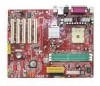
Getting Started Thank you for purchasing K8T Neo (MS-6702 v1.X) ATX mainboard. The K8T Neo is based on VIA® K8T800 North Bridge & VT8237 South Bridge chipsets and provides eight USB 2.0 ports for high-speed data transmission, RealTek ALC655 chip for 6-channel audio output, and a SPDIF interface for - MSI K8T800 | User Guide - Page 9
8x transfer mode h VIA® VT8237 chipset (487 BGA) - Integrated Faster Ethernet LPC - Integrated Hardware Sound Blaster/Direct Sound AC97 audio - Ultra DMA 66/100/133 master mode PCI EIDE controller - ACPI - Supports 2 Serial ATA ports - Supports 8 USB2.0 ports Main Memory h Supports DDR266/333/400 - MSI K8T800 | User Guide - Page 10
Getting Started Promise 20378 On-Board (Optional) h Supports 2 serial ATA plus 1 ATA133 - RAID 0, RAID 1 or RAID 0+1 is supported - RAID function work w/ATA133+SATA H/D or 2SATA H/D h Connect up to 2 SATA device and 2 ATA133 devices On-Board Peripherals h On-Board Peripherals include: - 1 floppy - MSI K8T800 | User Guide - Page 11
3 IDE 1 IDE 2 FDD 1 VIA VT6307 R e al Te k 8 110 S J4 Codec JAUD1 AGP Slot PCI Slot 1 PCI Slot 2 PCI Slot 3 PCI Slot 4 PCI Slot 5 VIA VT8237 SATA 1 SATA 2 JBAT1 JGS1 PW FA N 2 PW FA N 1 BATT + SER1 IDE 3 PROMISE PDC20378 SER2 JUSB1 JUSB2 JLED JIR1 JFP2 JFP1 MS-6702 v1.X ATX Mainboard - MSI K8T800 | User Guide - Page 12
Special Features Color Management MSI has a unified color management rule for some connectors on the mainboards, which helps you to install the memory modules, expansion cards and other peripherals devices more easily and conveniently. h Memory DDR DIMMs: Light Green h Intel spec IDE ATA66/100/133 - MSI K8T800 | User Guide - Page 13
MS-6702 ATX Mainboard Core Center The Core Center is a new utility you can find in the CD-ROM 'n'Quiet function, please click the Core Center Cool'n'Quiet icon, and then select Cool'n'Quiet mode. If User mode is selected, you will be able to adjust the CPU fan speed by sliding the adjusting bar. 1-6 - MSI K8T800 | User Guide - Page 14
red triangles in the left and right sides, two submenus will open for users to overclock, overspec or to adjust the thresholds of system to send out In the left sub-menu, you can configure the settings of FSB, Vcore, Memory Voltage and AGP Voltage by clicking the radio button in front of each item - MSI K8T800 | User Guide - Page 15
MS-6702 ATX Mainboard MSI Reminds You... To ensure that Cool'n'Quiet function is activated and not support Cool'n'Quiet function. 2. Run BIOS Setup, and select Frequency/Voltage Control. Under Frequency/Voltage Control, find Cool'n'Quiet Support, and set this item to "Enable." 3. Enter Windows, and - MSI K8T800 | User Guide - Page 16
Getting Started Core CellTM Chip By diagnosing the current system utilization, the CoreCell™ Chip automatically tunes your motherboard to the optimal state, leading to less noise, longer duration, more powersaving and higher performance. Features of CoreCell™ Speedster -- Advanced O.C. design. -- - MSI K8T800 | User Guide - Page 17
MS-6702 ATX Mainboard Dynamic Overclocking Technology Dynamic Overclocking Technology is the automatic overclocking function. It is designed to detect the load balance of CPU while running programs, and to adjust the best CPU frequency automatically. When the motherboard detects CPU is running - MSI K8T800 | User Guide - Page 18
online so that you don't need to search for the correct BIOS/driver version throughout the whole Web site. To use the function, you need to install the "MSI Live Update 3" application. After the installation, the "MSI Live Update 3" icon (as shown on the right) will appear on the screen. Double - MSI K8T800 | User Guide - Page 19
MS-6702 ATX Mainboard Live Monitor™ The Live Monitor™ is a tool used to schedule the search for the latest BIOS/drivers version on the MSI Web site. To use the function, you need to install the "MSI Live Update 3" application. After installation, the "MSI MSI's products for users to inquire. 1-12 - MSI K8T800 | User Guide - Page 20
if the processor is dam- 3 4 aged or not installed properly. Early Chipset Initialization Memory Detection Test - Testing onboard memory size. The D-LED will hang if the memory module is damaged or not installed properly. Decompressing BIOS image to RAM for fast booting. Initializing Keyboard - MSI K8T800 | User Guide - Page 21
MS-6702 ATX Mainboard D-Bracket™ 2 Description Processor Initialization 1 2 - This will show information BIOS Sign On - This will start showing information about logo, processor brand name, etc... Testing Base and Extended Memory - Teting base memory from 240K to 640K and extended memory - MSI K8T800 | User Guide - Page 22
2. Hardware Setup Hardware Setup This chapter tells you how to install the CPU, memory modules, and expansion cards, as well as how to setup the jumpers on the mainboard. Also, it provides the instructions on connecting the peripheral devices, such as the mouse, keyboard, etc. While doing the - MSI K8T800 | User Guide - Page 23
MS-6702 ATX Mainboard Quick Components Guide CPU, p.2-3 CFAN1, p.2-19 SFAN1, p.2-19 DDR DIMMs, p.2-9 Back Panel I/O, p.2-13 JPW1, p.2-12 AGP Slot, p.2-27 PCI Slots, p.2-27 J4, p.2-20 JAUD1, p.2-24 JCASE1, p.2-18 ATX, p.2- - MSI K8T800 | User Guide - Page 24
cooling fan, contact your dealer to purchase and install them before turning on the computer. MSI Reminds You... Overheating Overheating will seriously damage the to ensure the safety of CPU. Overclocking This motherboard is designed to support overclocking. However, please make sure your components - MSI K8T800 | User Guide - Page 25
MS-6702 ATX Mainboard CPU Installation Procedures for Socket 754 1. Please turn off the power and unplug the power cord before installing the CPU. 2. not be seen. Please note that any violation of the correct installation procedures may cause permanent damages to your mainboard. 5. Press the CPU - MSI K8T800 | User Guide - Page 26
fan attached on the top to prevent overheating. If you do not have the heat sink and cooling fan, contact your dealer to purchase and install them before turning on the computer. 1. Detach the shield of the backplate's paster. 2. Turn over the mainboard, and - MSI K8T800 | User Guide - Page 27
MS-6702 ATX Mainboard 3. Turn over the mainboard again, and place the mainboard on the flat surface. Locate the two screw holes of the mainboard. 4. Align the - MSI K8T800 | User Guide - Page 28
6. Press down the other end of the clip to fasten the cooling set on the top of the retention mechanism. Hardware Setup 7. Locate the Fix Lever, Saftey Hook and the Fixed Bolt. Lift up the intensive fixed lever. Safety Hook Fixed Lever Fixed Bolt 2-7 - MSI K8T800 | User Guide - Page 29
MS-6702 ATX Mainboard 8. Fastened down the lever. 9. Make sure the safety hook completely clasps the fixed bolt of the retention mechanism. MSI Reminds You... While disconnecting the Safety Hook from the fixed bolt, it is necessary to keep an eye on your fingers, because once the Safety - MSI K8T800 | User Guide - Page 30
for 184-pin DDR SDRAM DIMM (Double In-Line Memory Module) modules and supports the memory size up to 2GB. You can install PC3200/DDR400, PC2700/DDR333, PC2100/ DDR266 or PC1600/DDR200 unbuffered DIMM modules on the DDR DIMM slots (DDR 1~3). Plugging memories in DIMM1 and DIMM2 makes the system reach - MSI K8T800 | User Guide - Page 31
MS-6702 ATX Mainboard DDR DIMM Module Combination Install at least one DIMM module on the slots. Memory modules can be installed on the slots in any order. You can install either single- or doublesided modules to meet your own needs. Memory modules can be installed in any combination as follows: - MSI K8T800 | User Guide - Page 32
Hardware Setup Recommended Memory Combination List DIMM Slot DIMM1 DIMM2 DIMM3 S - - - S - - - S D - - - D - - - D S S - S - S S D - S - D D S - D - S D D - D - D - S S D S S S S S - S D - D S - D D S S D S D S S D D D D S D - MSI K8T800 | User Guide - Page 33
MS-6702 ATX Mainboard Power Supply The mainboard supports ATX power supply for the power system. Before inserting the power supply connector, always make sure that all components are installed 2 GND 3 12V 4 12V MSI Reminds You... Power supply of 300 (and up) watt is highly - MSI K8T800 | User Guide - Page 34
Hardware Setup Back Panel The back panel provides the following connectors: Mouse Parallel Line-In Line-Out MIC SPDIF LAN Out (Optional) Keyboard COM A Mini 1394 Port (Optional) 1394 Port (Optional) USB Ports Rear Speaker-Out Center/Subwoofer Speaker-Out SPDIF-Out Mouse Connector The - MSI K8T800 | User Guide - Page 35
MS-6702 ATX Mainboard USB 2.0 Connectors The mainboard provides a UHCI (Universal Host Controller Interface) Universal Serial Bus root for attaching USB devices such as keyboard, mouse or other USB-compatible devices. You can plug the USB device directly into the connector. 1 2 3 4 5 6 7 8 USB - MSI K8T800 | User Guide - Page 36
send/ receive 16 bytes FIFOs. You can attach a serial mouse or another serial device directly to the connector. 1 2 3 4 5 PIN 1 2 3 4 6 provides one standard RJ-45 jack for connection to Local Area Network (LAN). You can connect a network cable to the LAN jack. Activity Indicators RJ-45 LAN - MSI K8T800 | User Guide - Page 37
MS-6702 ATX Mainboard Audio Port Connectors The left 3 audio jacks are for 2-channel mode for stereo speaker output: Line Out is a connector for Speakers or Headphones. Line In is used for external CD player, Tape player, or other audio devices. Mic is a connector for microphones. However, there is - MSI K8T800 | User Guide - Page 38
Port Connector: LPT1 The mainboard provides a 25-pin female centronic connector as LPT. A parallel port is a standard printer port that supports Enhanced Parallel Port (EPP) and Extended Capabilities Parallel Port (ECP) mode. 13 1 25 14 Pin Definition PIN SIGNAL DESCRIPTION 1 STROBE - MSI K8T800 | User Guide - Page 39
MS-6702 ATX Mainboard Connectors The mainboard provides connectors to connect to FDD, IDE HDD, case, modem, LAN, USB Ports, IR module and CPU/System/Power Supply FAN. Floppy Disk Drive Connector: FDD1 The mainboard provides a standard floppy disk drive connector that supports 360K, 720K, 1.2M, 1.44M - MSI K8T800 | User Guide - Page 40
SENSOR CFAN1 GND +12V SENSOR SFAN1 GND +12V SENSOR PWFAN1 GND +12V SENSOR PWFAN2 MSI Reminds You... 1. Always consult the vendors for proper CPU cooling fan. 2. CFAN1 supports the fan control. You can install Core Center utility that will automatically control the CPU fan speed according to the - MSI K8T800 | User Guide - Page 41
MS-6702 ATX Mainboard Front Panel Connectors: JFP1 & JFP2 The mainboard provides two front panel connectors for electrical connection to the front panel switches and LEDs. JFP1 and JFP2 are compliant with Intel® Front Panel I/O Connectivity Design Guide MSI audio connector. J4 R GND L 2-20 - MSI K8T800 | User Guide - Page 42
reserved for future BIOS) and other devices. IDE1 IDE2 IDE1 MSI Reminds You... If you install two hard disks on cable, you must configure the second drive to Slave mode by setting its jumper. Refer to the hard disk documentation supplied by hard disk vendors for jumper setting instructions - MSI K8T800 | User Guide - Page 43
can connect to 1 hard disk device. Please refer to Serial ATA/Serial ATA Raid manual for detail software installation procedure. 71 SATA1 SATA2 Serial ATA/Serial ATA RAID Connectors controlled by Promise 20378: IDE3, SER1 & SER2 The brand new Promise 20378 chipset supports one IDE connector IDE3 and - MSI K8T800 | User Guide - Page 44
Optional Serial ATA cable Hardware Setup Take out the dust cover and connect to the hard disk devices Connect to SER1 / SER2 or SATA1 / SATA2 MSI Reminds You... Please do not fold the serial ATA cable in a 90-degree angle, since this will cause the loss of data during the transmission. - MSI K8T800 | User Guide - Page 45
MS-6702 ATX Mainboard Front Panel Audio Connector: JAUD1 The JAUD1 front panel audio connector allows you to connect to the front panel audio and is compliant with Intel® Front Panel I/O Connectivity Design Guide. 2 1 10 9 JAUD1 JAUD1 Pin Definition PIN SIGNAL DESCRIPTION 1 AUD_MIC Front - MSI K8T800 | User Guide - Page 46
with a JLED connector for you to connect to DBracket™ 2. D-Bracket™ 2 is a USB Bracket that supports both USB1.1 & 2. 0 spec. It integrates four LEDs and allows users to identify system problem through 16 various combinations of LED signals. For definitions of 16 signal combinations, please refer to - MSI K8T800 | User Guide - Page 47
MS-6702 ATX Mainboard Jumper The motherboard provides the following jumper for you to set the computer's function. This section will explain how to change your motherboard clear data. Follow the instructions below to clear the data: 1 JBAT1 1 1 3 Keep Data 3 Clear Data MSI Reminds You... You - MSI K8T800 | User Guide - Page 48
card. AGP is an interface specification designed for the throughput demands of 3D graphics. It introduces a 66MHz, 32-bit channel for the graphics controller to directly access main memory. The slot supports 8x/4x/2x/1x AGP card. PCI (Peripheral Component Interconnect) Slots The PCI slots allow - MSI K8T800 | User Guide - Page 49
MS-6702 ATX Mainboard PCI Interrupt Request Routing The IRQ, acronym of interrupt request line and pronounced I-R-Q, are hardware lines over which devices can send interrupt signals to the microprocessor. The PCI IRQ pins are typically connected to the PCI bus INT A# ~ INT D# pins as follows: PCI - MSI K8T800 | User Guide - Page 50
This chapter provides information on the BIOS Setup program and allows you to configure the system for optimum use. You may need to run the Setup program when: ” An error message appears - MSI K8T800 | User Guide - Page 51
MS-6702 ATX Mainboard Entering Setup Power on the computer and the system will start POST (Power On Self Test) process. When the message below appears on the screen, press key to enter Setup. DEL:Setup F11:Boot Menu F12:Network boot TAB:Logo If the message disappears before you respond and you - MSI K8T800 | User Guide - Page 52
Main Menu. Main Menu The main menu displays the setup categories the BIOS supplies. You can use the arrow keys ( ↑↓ ) to BIOS setup program contains two kinds of default settings: the BIOS Setup and High Performance defaults. BIOS Setup defaults provide stable performance settings for all devices - MSI K8T800 | User Guide - Page 53
MS-6702 ATX Mainboard The Main Menu Once you enter AMIBIOS NEW SETUP UTILITY, the time, date etc. Advanced BIOS Features Use this menu to setup the items of AMI® special enhanced features. Advanced Chipset Features Use this menu to change the values in the chipset registers and optimize your system - MSI K8T800 | User Guide - Page 54
for frequency/voltage control. Set Supervisor Password Use this menu to set Supervisor Password. Set User Password Use this menu to set User Password. Load High Performance Defaults Use this menu to load the BIOS values for the best system performance, but the system stability may be affected. Load - MSI K8T800 | User Guide - Page 55
MS-6702 ATX Mainboard Standard CMOS Features The items inside STANDARD CMOS SETUP menu are divided into 9 categories. Each category includes The date from 1 to 31 can be keyed by numeric function keys. year The year can be adjusted by users. day Day of the week, from Sun to Sat, determined by - MSI K8T800 | User Guide - Page 56
512 MB un- der Windows and DOS, or Disabled the type of floppy drives installed. Available options: Not Installed, 1.2 MB 5¼, 720 BIOS will issue a virus warning message and beep if a write to the boot sector or the partition table of the HDD is attempted. Setting options: Disabled and Enabled. MSI - MSI K8T800 | User Guide - Page 57
MS-6702 ATX Mainboard Advanced BIOS Features Quick Boot Setting the item to Enabled allows the system to enter the sub-menu screen. 1st/2nd/3rd Boot Device The items allow you to set the sequence of boot devices where AMIBIOS attempts to load the operating system. S.M.A.R.T. for Hard Disks - MSI K8T800 | User Guide - Page 58
Lock key when the system is powered on. Setting to Off will allow end users to use the arrow keys on the numeric keypad. Setting options: On, Off Floppy Drive Seek This setting causes the BIOS to search for floppy disk drives at boot time. When enabled, the BIOS will activate the floppy disk drives - MSI K8T800 | User Guide - Page 59
MS-6702 ATX Mainboard Internal Cache Cache memory is additional memory that is much faster than conventional DRAM (system memory). When the CPU requests data, the system transfers the requested data from the main DRAM into cache memory select the MPS version supported by your operating system. To - MSI K8T800 | User Guide - Page 60
BIOS Setup Advanced Chipset Features MSI Reminds You... Change these settings only if you are familiar with the chipset. System When it is set to Manual in "Memclock Mode", user can place an artificial memory clock limit on the system. Please note that memory is prevented from running faster - MSI K8T800 | User Guide - Page 61
MS-6702 ATX Mainboard Bank Interleaving This field selects 2-bank or 4-bank interleave for the installed SDRAM. Disable the function if 16MB SDRAM is installed and allows internal address counter to properly generate the next memory location. The bigger the size, the faster the DRAM performance - MSI K8T800 | User Guide - Page 62
Fast Write technology allows the CPU to write directly to the graphics card without passing anything through the system memory and improves the AGP 4X speed. Select Enabled only when the installed AGP card supports this function. Settings: Enabled, Disabled. AGP Aperture Size This setting controls - MSI K8T800 | User Guide - Page 63
MS-6702 ATX Mainboard Power Management Features MSI Reminds You... S3-related functions described in this section are available only when your BIOS supports S3 sleep mode. ACPI Standby State This item specifies the power saving modes for ACPI function. If your operat- ing system supports ACPI, - MSI K8T800 | User Guide - Page 64
driver of the card does not support the initialization feature, the display may work abnormally or not function after resuming from S3. USB Device Wakeup From S3 This item allows the activity of the USB device items specify if the BIOS will monitor the activity of CPU overheating problem. Power - MSI K8T800 | User Guide - Page 65
MS-6702 ATX Mainboard After AC Power Loss This setting specifies whether your system activity or input signal of the specified hardware peripheral or component is detected. Settings: Enabled, Disabled. MSI Reminds You... For "Wake-Up Key" function, the option "Specific Key" refers to the password - MSI K8T800 | User Guide - Page 66
BIOS Setup Alarm Date/Hour/Minute/Second If Resume By Alarm is set to Enabled, Date 01 ~ 31, Every Day Alarm Hour 00 ~ 23 Alarm Minute 00 ~ 59 Alarm Second 00 ~ 59 MSI Reminds You... If you have changed this setting, you must let the system boot up until it enters the operating system - MSI K8T800 | User Guide - Page 67
MS-6702 ATX Mainboard PNP/PCI Configurations This section describes configuring the PCI bus system and PnP (Plug & Play) feature. PCI, or Peripheral Component Interconnect, is a system which allows I/O devices Memory) is where the BIOS stores resource information for both PNP and non-PNP devices - MSI K8T800 | User Guide - Page 68
device can conduct transactions for a longer time and thus improve the effective PCI bandwidth. For better PCI performance, you should set the item to higher values. Settings range from 32 to 248 at a 32 increment. Primary Graphics BIOS to automatically determine the IRQ line for each PCI slot. 3-19 - MSI K8T800 | User Guide - Page 69
MS-6702 ATX Mainboard Integrated Peripherals OnBoard PCI Controller Press to enter the sub-menu screen. LAN Controller, P20378 S.ATA Controller, 1394 Controller, Audio Controller Set these options to Enabled (SATA or RAID for P20378 S.ATA Controller) to enable the controllers of these four - MSI K8T800 | User Guide - Page 70
This setting controls the onboard V-Link Data 2X Support. Setting options: Enabled, Disabled. Floopy Disk Controller This is used to enable or disable the onboard Floppy controller. Option Auto Enabled Disabled Description BIOS will automatically determine whether to enable the onboard Floppy - MSI K8T800 | User Guide - Page 71
onboard USB ports. Setting options: Disabled, 2 USB Ports, 4 USB Ports, 6 USB Ports USB Device Legacy Support Set to All Device if you need to use any USB device in the operating system that does not support or have any USB driver installed, such as DOS and SCO Unix. Set to No Mice only if you want - MSI K8T800 | User Guide - Page 72
BIOS Setup PC Health Status This section shows the status of your CPU, fan, overall system status, etc. +12.0V, -12.0V, -5.0V, Battery, +5V SB These items display the current status of all of the monitored hardware devices/components such as CPU voltages, temperatures and all fans' speeds. 3-23 - MSI K8T800 | User Guide - Page 73
function, it is always recommended to have the memories plugged in DIMM1. For more information about Cool'n'Quiet, please refer the MSI Special Features at Chapter 1, or visit MSI's website at www.msi. com.tw. Spread Spectrum When the motherboard's clock generator pulses, the extreme values (spikes - MSI K8T800 | User Guide - Page 74
BIOS and to adjust the best CPU frequency automatically. When the motherboard detects CPU is running programs, it will speed up CPU automatically MSI Reminds You... Even though the Dynamic Overclocking Technology is more stable than manual overclocking, basically, it is still risky. We suggest user - MSI K8T800 | User Guide - Page 75
MS-6702 ATX Mainboard CPU FSB Clock This item allows you to select the to adjust the CPU clock multiplier (ratio) and CPU corevoltage (Vcore). These settings offer users a tool to overclock the system. MSI Reminds You... Changing CPU Vcore could result in the instability of the system; therefore, it - MSI K8T800 | User Guide - Page 76
BIOS Setup Set Supervisor/User Password When you select this function, a message as below will appear on the screen: Type the password, up to six characters in length, and press . The password typed now will replace any previously set password from CMOS memory. You will be prompted to - MSI K8T800 | User Guide - Page 77
MS-6702 ATX Mainboard Load High Performance/BIOS Setup Defaults The two options on the main menu allow users to restore all of the BIOS settings to High Performance defaults or BIOS the problem. For more information, refer to "Clear CMOS Jumper:JBAT1" in Chapter 2. When you select Load BIOS Setup - MSI K8T800 | User Guide - Page 78
ALC655 chip, which provides support for 6-channel audio output, including 2 Front, 2 Rear, 1 Center and 1 Subwoofer channel. ALC655 allows the board to attach 4 or 6 speakers for better surround sound effect. The section will tell you how to install and use 4-/6-channel audio function on the board - MSI K8T800 | User Guide - Page 79
to 4-/6-channel audio operations. Follow the procedures described below to install the drivers for different operating systems. Installation for Windows 98SE/ME/2000/XP For Windows® 2000, you must install Windows® 2000 Service Pack2 or later before installing the driver. The following illustrations - MSI K8T800 | User Guide - Page 80
Using 4- or 6-Channel Audio Function 3. CClliicckkNNeexxttttooiinnssttaalllltthheeAACC''9977AAuuddiioossooffttwwaarree.. 4. CClliicckkFFiinniisshhttoorreessttaarrtttthheessyysstteemm.. Click here Select this option Click here A-3 - MSI K8T800 | User Guide - Page 81
MS-6702 ATX Mainboard Software Configuration After installing the audio driver, you are able to use the 4-/6-channel audio feature now. Click the audio icon from the window tray at the lowerright corner of the screen to activate the AC97 Audio Configuration. Sound Effect Here you can select a sound - MSI K8T800 | User Guide - Page 82
function which will automatically remove human voice (lyrics) and leave melody for you to sing the song. Note that this function applies only for 2-channel audio operation. Just check the Voice Cancellation box and then click OK to activate the Karaoke function. A-5 - MSI K8T800 | User Guide - Page 83
MS-6702 ATX Mainboard Equalizer Here you regulate each equalizer for current playing digital sound sources. You may choose the provided sound effects, and the equalizer will adjust automatically. If you like, you may also load an equalizer setting or make an new equalizer setting to save - MSI K8T800 | User Guide - Page 84
function and speakers. 1. This mainboard provide two different kinds of audio jacks combination. According to the mainboard to select the proper audio configuration below which is identical to the audio jack in your mainboard. For this K8T Neo mainboard, you will have to choose 6CH + S/PDIF (Optical - MSI K8T800 | User Guide - Page 85
MS-6702 ATX Mainboard 2. Select a desired multi-channel operation from Number of Speaker. a. tab to test each connected speaker to ensure if 4- or 6channel audio operation works properly. If any speaker fails to make sound, then check whether the cable is inserted firmly to the connector or - MSI K8T800 | User Guide - Page 86
light up and make testing sound. MSI Reminds You... 1. 6 speakers appear on the "Speaker Test" tab only when you select "6-Channel Mode" in the "Number of Speakers" column in "Speaker Configuration" tab. If you select "4-Channel Mode", only 4 speakers appear on the window. 2. While you are testing - MSI K8T800 | User Guide - Page 87
MS-6702 ATX Mainboard HRTF Demo In this tab you may adjust your HRTF (Head Related Transfer Functions) 3D positional audio before playing 3D audio applications like gaming. You may also select different environment to choose the most suitable environment you like. A-10 - MSI K8T800 | User Guide - Page 88
Using 4- or 6-Channel Audio Function General In this tab it provides some information about this AC97 Audio Configuration utility, including Audio Driver Version, DirectX Version, Audio Controller & AC97 Codec. You may also select the language of this utility by choosing from the Language list. A-11 - MSI K8T800 | User Guide - Page 89
MS-6702 ATX Mainboard Using 2-, 4- & 6- Channel Audio Function MSI Reminds You... This mainboard provide two different kinds of audio jacks combination. According to the mainboard to select the proper audio configuration below. 6CH + S/PDIF (Optical & Coaxial) Connecting the Speakers When you have - MSI K8T800 | User Guide - Page 90
Using 4- or 6-Channel Audio Function „ 4-Channel Mode for 4-Speaker Output Refer to the following diagram and caption for the function of each phone jack on the back panel when 4- - MSI K8T800 | User Guide - Page 91
MS-6702 ATX Mainboard „ 6-Channel Mode for 4-Speaker Output Refer to the following diagram and caption for the function of each phone jack on the back panel - MSI K8T800 | User Guide - Page 92
SPDIF Coaxial jack 2 4 3 „ 4-Channel Mode for 4-Speaker Output The audio jacks on the back panel always provide 2-channel analog audio output function, however these audio jacks can be transformed to 4- or 6channel analog audio jacks by selecting the corresponding multi-channel operation from No - MSI K8T800 | User Guide - Page 93
MS-6702 ATX Mainboard „ 6-Channel Mode for 6-Speaker Output Refer to the are converted to Line Out function when 6-Channel Mode for 6- Speaker Output is selected. 3 MSI Reminds You... If the audio signals coming from the Center and Subwoofer speaker are swapped when you play video or music on - MSI K8T800 | User Guide - Page 94
array support. 9. Windows-based RAID configure and management software tool. (Compatible with BIOS) 10. Supports hot-swap failed disk drive in RAID 1 array. 11. ATA SMART function support. 12. Microsoft Windows 98, Me, NT4.0, 2000, XP operating systems support. 13. Event log for easy troubleshooting - MSI K8T800 | User Guide - Page 95
MS-6702 ATX Mainboard Introduction This section gives a brief introduction on the RAID-related background knowledge and a brief introduction on VIA SATA RAID Host Controller. For users wishing to install their VIA SATA RAID driver and RAID software, proceed to Driver and RAID Software Installation - MSI K8T800 | User Guide - Page 96
VIA VT8237 Serial ATA RAID Introduction RAID 0 (Striping) RAID 0 reads and writes sectors of data interleaved member. The striping block size can be set from 4KB to 64KB. RAID 0 does not support fault tolerance. RAID 1 (Mirroring) RAID 1 writes duplicate data onto a pair of drives and reads both sets - MSI K8T800 | User Guide - Page 97
MS-6702 ATX Mainboard BIOS Configuration When the system powers on during the POST (Power-On Self Test) process, press key to enter the BIOS configuration. The Serial ATA RAID volume may be configured using the VIA Tech. RAID BIOS. Always use the arrow keys to navigate the main menu, use up - MSI K8T800 | User Guide - Page 98
VIA VT8237 Serial ATA RAID Introduction Create Disk Array Use the up and down arrow keys to select the Create Array command and press . MSI RAID 1 or RAID 0/1 is selected, an option list will popup and enable the users to select Create only or Create and duplicate. Create only will allow BIOS - MSI K8T800 | User Guide - Page 99
Setup" and the other one is "Select Disk Drives". Auto Setup allows BIOS to select the disk drives and create arrays automatically, but it does not duplicate the mirroring drives even if the user selected Create and duplicate for RAID 1. It is recommended all disk drives are new ones when wanting to - MSI K8T800 | User Guide - Page 100
VIA VT8237 Serial ATA RAID Introduction MSI Reminds You... Even though 64KB is the recommended setting for most users, you should choose the block size value which is best suited to your specific RAID usage model. 4KB: For specialized usage models requiring 4KB blocks 8KB: For specialized usage - MSI K8T800 | User Guide - Page 101
MS-6702 ATX Mainboard Delete Disk Array A RAID can be deleted after it has been created. To delete a RAID, use the following steps: 1. disk array will destroy all the data on the disk array except RAID 1 arrays. When a RAID is deleted, the data on these two hard disk drives will be reserved and become - MSI K8T800 | User Guide - Page 102
VIA VT8237 Serial ATA RAID Introduction Create and Delete Spare Hard Drive If a RAID 1 array is created and there are drives that do not belong to other arrays, the one that has a capacity which is equal to or greater than the array capacity can be selected as a spare drive for the RAID 1 array. - MSI K8T800 | User Guide - Page 103
MS-6702 ATX Mainboard View Serial Number of Hard Drive Highlight Serial Number View and press . Use arrow key to select a drive, the selected drive's serial - MSI K8T800 | User Guide - Page 104
VIA VT8237 Serial ATA RAID Introduction Duplicate Critical RAID 1 Array When booting up the system, BIOS will detect if the RAID 1 array has any inconsistencies between user data and backup data. If BIOS detects any inconsistencies, the status of the disk array will be marked as critical, and BIOS - MSI K8T800 | User Guide - Page 105
MS-6702 ATX Mainboard Rebuild Broken RAID 1 Array When booting up the system, BIOS will detect if any member disk drives of RAID has failed or is absent. If BIOS detects any disk drive failures or missing disk drives, the status of the array will be marked as broken. If BIOS detects a broken RAID 1 - MSI K8T800 | User Guide - Page 106
VIA VT8237 Serial ATA RAID Introduction 3. Choose Replacement Drive and Rebuild: This item enables users to select an already-connected hard drive to rebuild the broken data on the selected hard drive. 4. Continue to boot: This item enables BIOS to skip the problem and continue booting into OS. B-13 - MSI K8T800 | User Guide - Page 107
will now load all device files and then continue the Windows XP installation h Existing Windows XP Driver Installation 1. Insert the MSI CD into the CD-ROM drive. 2. The CD will auto-run and the setup screen will appear. 3. Under the Driver tab, click on VIA SATA RAID Utility. 4. The drivers will be - MSI K8T800 | User Guide - Page 108
0 arrays in the Windows* XP operating system. This version of VIA SATA RAID Utility contains the following key features: h Serial ATA RAID driver for Windows XP h VIA SATA RAID utility h RAID0 and RAID1 functions Insert the MSI CD and click on the VIA SATA RAID Utility to install the software. B-15 - MSI K8T800 | User Guide - Page 109
MS-6702 ATX Mainboard The InstallShield Wizard will begin automatically for installation. Click on the Next button to proceed the installation in the welcoming window. Put a check mark in the check box to install the feature you want. Then click Next button to proceed the installation. B-16 - MSI K8T800 | User Guide - Page 110
VT8237 Serial ATA RAID Introduction Using VIA RAID Tool Once the installation is complete, go to Start ---> Programs --->VIA -->raid_tool.exe to enable VIA RAID Tool. After the software is finished installation, it will automatically started every time Windows is initiated. You may double-click on - MSI K8T800 | User Guide - Page 111
MS-6702 ATX Mainboard The main interface is divided into two windows and the SATA RAID in KT6 Delta only has the feature of monitoring the statuses of RAID 0 and RAID 1. Click on o r button to determine the viewing type of left window pane. There are two viewing types: By controllers and by device - MSI K8T800 | User Guide - Page 112
VIA VT8237 Serial ATA RAID Introduction Click on the plus (+) symbol next to Array 0---RAID 0 to see the details of each disk. You may also use the same o r button to view the statuses of Array 0---RAID 1. B-19 - MSI K8T800 | User Guide - Page 113
MS-6702 ATX Mainboard Click on the plus (+) symbol next to Array 0---RAID 1 to see the details of each disk. B-20
-
 1
1 -
 2
2 -
 3
3 -
 4
4 -
 5
5 -
 6
6 -
 7
7 -
8
-
9
-
10
-
11
-
12
-
13
-
14
-
15
-
16
-
17
-
18
-
19
-
20
-
21
-
22
-
23
-
24
-
25
-
26
-
27
-
28
-
29
-
30
-
31
-
32
-
33
-
34
-
35
-
36
-
37
-
38
-
39
-
40
-
41
-
42
-
43
-
44
-
45
-
46
-
47
-
48
-
49
-
50
-
51
-
52
-
53
-
54
-
55
-
56
-
57
-
58
-
59
-
60
-
61
-
62
-
63
-
64
-
65
-
66
-
67
-
68
-
69
-
70
-
71
-
72
-
73
-
74
-
75
-
76
-
77
-
78
-
79
-
80
-
81
-
82
-
83
-
84
-
85
-
86
-
87
-
88
-
89
-
90
-
91
-
92
-
93
-
94
-
95
-
96
-
97
-
98
-
99
-
100
-
101
-
102
-
103
-
104
-
105
-
106
-
107
-
108
-
109
-
110
-
111
-
112
-
113
 |
 |
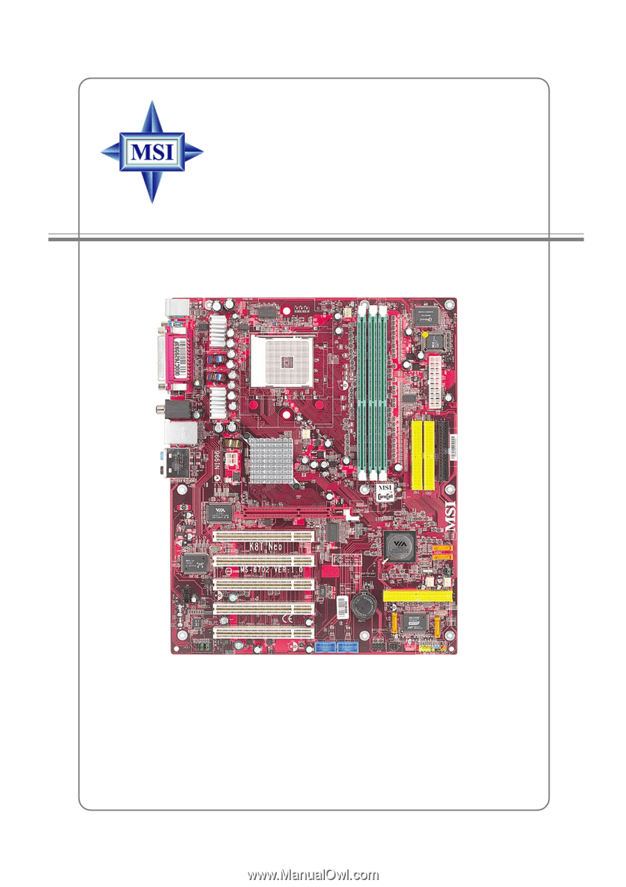
K8T Neo
Version 1.1
G52-M6702X7
MS-6702 (v1.X) ATX Mainboard