MSI MS 6378 User Guide
MSI MS 6378 - Motherboard - Micro ATX Manual
 |
View all MSI MS 6378 manuals
Add to My Manuals
Save this manual to your list of manuals |
MSI MS 6378 manual content summary:
- MSI MS 6378 | User Guide - Page 1
MSI MICRO-STAR INTERNATIONAL MS-6378 (v3.X) Micro-ATX Mainboard Version 3.1 G52-MA00585 i - MSI MS 6378 | User Guide - Page 2
and used in accordance with the instruction manual, may cause harmful interference to radio approved by the party responsible for compliance could void the user's authority to operate the equipment. Notice 2 Shielded interface MS-6378 Tested to comply with FCC Standard For Home or Office Use ii - MSI MS 6378 | User Guide - Page 3
Edition Mar. 2002 Copyright Notice The material in this document is the intellectual property of MICRO-STAR INTERNATIONAL. We take every care in the preparation of this document, but no guarantee is given as to the correctness of its contents. Our products are under continual improvement and we - MSI MS 6378 | User Guide - Page 4
instructions carefully. 2. Keep this User's Manual for future reference. 3. Keep this equipment away from humidity. 4. Lay this equipment on a reliable flat surface before setting the following situations arises, get the equipment checked by a service personnel: z The power cord or plug is damaged z - MSI MS 6378 | User Guide - Page 5
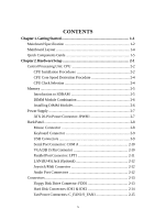
1. Getting Started 1-1 Mainboard Specification 1-2 Mainboard Layout 1-4 Quick Components Guide 1-5 Chapter 2. Hardware Setup 2-1 Central Processing Unit: CPU 2-2 CPU Installation Procedures 2-2 CPU Core Speed Derivation Procedure 2-4 CPU Clock Selection 2-4 Memory 2-5 Introduction to SDRAM - MSI MS 6378 | User Guide - Page 6
: JUSB1 2-19 Chassis Intrusion Switch Connector: JCASE1 2-19 Wake On Ring Connector: JMDM1 2-20 Wake On LAN Connector: JWOL1 2-20 Jumpers 2-21 Clear CMOS Jumper: JBAT1 2-21 CPU Clock Selection Jumper: JFSB1 2-22 Slots 2-23 PCI Slots 2-23 CNR (Communication Network Riser) Slot 2-23 ISA Slot - MSI MS 6378 | User Guide - Page 7
Set Supervisor/User Password 3-32 Glossary ...G-1 vii - MSI MS 6378 | User Guide - Page 8
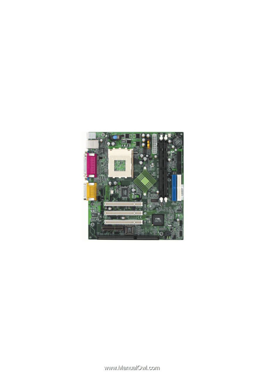
MS-6378 (v3.X) Micro-ATX mainboard. The MS-6378 (v3.X) is a high-performance computer mainboard based on VIA® Apollo KLE133 (VT8361+VT82C686B) chipset for optimal system efficiency. Designed to fit the advanced AMD® Athlon™, Athlon™ XP and Duron™ processors in the 462 pin package, the motherboard - MSI MS 6378 | User Guide - Page 9
Chapter 1 Mainboard Specification CPU Supports Socket 462 for AMD® Duron™/Athlon™ /Athlon™ XP processors Supports Athlon XP 1900+ MHz and higher processor Chipset VIA® VT8361 chipset (552 BGA) - FSB @200/266MHz - Integrated Trident Blade 2D/3D video accelerator - PCI advanced high performance memory - MSI MS 6378 | User Guide - Page 10
which records your mainboard specifications. Dimension Micro-ATX Form Factor: 24.4 cm (L) x 21.5 cm (W) Mounting 6 mounting holes Others Suspend to Disk S4/S3 Plug and Play function Supports PCI 2.2 Hardware Monitoring (optional) Modem (External/Internal) Ring Wake up Function LAN Wake up Function - MSI MS 6378 | User Guide - Page 11
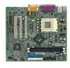
Mainboard Layout Top : mouse Bottom: keyboard Top: LAN Jack(optional) Bottom: USB ports SOCKET 462 Top : Parallel Port Bottom: COM Port & VGA Port ATX Slot (optional) BIOS VIA VT82C686B JCASE1 JUSB1 JBAT1 JFP2 JMDM1 JAUD2 JIR1 JFP1 MS-6378 (v3.X) Micro-ATX Mainboard IDE 1 IDE 2 1-4 - MSI MS 6378 | User Guide - Page 12
Guide Getting Started Component Function DIMM 1~2 Installing memory modules Socket 462 Installing CPU C_FAN1 Connecting to CPUFAN S_FAN1 Connecting to SYSFAN ATX modem module JWOL1 Connecting to LAN card JBAT1 Clearing CMOS data JFSB1 Setting CPU Front Side Bus frequency JCD1 - MSI MS 6378 | User Guide - Page 13
, the components will not work properly. Use a grounded wrist strap before handling computer components. Static electricity may damage the components. TOPICS Central Processing Unit: CPU 2-2 Memory 2-5 Power Supply 2-7 Back Panel 2-8 Connectors 2-13 Jumpers 2-21 Slots 2-23 2-1 - MSI MS 6378 | User Guide - Page 14
CPU The mainboard supports AMD® Athlon™, Athlon™ XP and Duron™ processors in the 462 pin package. The mainboard uses a CPU socket called Socket A for easy CPU installation. When you are installing the CPU, make sure the CPU before turning on the computer. CPU Installation Procedures 1. Pull the - MSI MS 6378 | User Guide - Page 15
a speed of 600MHz and above requires LARGER heatsink and fan. You also need to add thermal grease between the CPU and heatsink to improve heat dissipation. Then, make sure that the CPU and heatsink are securely fastened and in good contact with each other. These are needed to prevent damaging the - MSI MS 6378 | User Guide - Page 16
information on the issue, refer to CPU Clock Selection Jumper: JFSB1 later in this chapter. WARNING! Overclocking This motherboard is designed to support overclocking. However, please make sure your components are able to tolerate such abnormal setting, while doing overclocking. Any attempt to - MSI MS 6378 | User Guide - Page 17
Setup Memory The mainboard provides 2 sockets for 168-pin unbuffered SDRAM DIMM (Double In-Line Memory Module) modules and supports the memory size up to 1 GB. The socket supports 256MB technology. DIMM Slots (DIMM 1~2) Introduction to SDRAM Synchronous DRAM (SDRAM) is a type of dynamic RAM memory - MSI MS 6378 | User Guide - Page 18
modules can be installed in any combination as follows: Slot Memory Module DIMM 1 S/D (Bank 0 & 1) DIMM 2 S/D (Bank 2 & 3) Maximum System Memory Supported S: Single Side D: Double Side Total Memory 32MB~512MB 32MB~512MB 32MB~1GB Installing DIMM Modules The DIMM slot has 2 Notch Keys - MSI MS 6378 | User Guide - Page 19
Hardware Setup Power Supply The mainboard supports ATX power supply for the power system. Before inserting the power supply connector, always make sure that all components are installed properly to ensure that no damage will be caused. ATX 20-Pin Power Connector: JPWR1 This connector allows you to - MSI MS 6378 | User Guide - Page 20
Chapter 2 Back Panel The Back Panel provides the following connectors: LAN M o u s e (optional) Parallel Midi/Joystick Keyboard USB COM VGA L-out L-in MIC Mouse Connector The mainboard provides a standard PS/2® mouse mini DIN connector for attaching a PS/2® mouse. You can plug a PS/2® mouse - MSI MS 6378 | User Guide - Page 21
Female) 5 6 Keyboard DATA NC GND VCC Keyboard Clock NC Keyboard DATA No connection Ground +5V Keyboard clock No connection USB Connectors The mainboard provides a UHCI (Universal Host Controller Interface) Universal Serial Bus root for attaching USB devices such as keyboard, mouse or other USB - MSI MS 6378 | User Guide - Page 22
COM A The mainboard offers one 9-pin Serial Out or Transmit Data Data Terminal Ready) Ground Data Set Ready Request To Send Clear To Send Ring Indicate VGA 5 1 15 11 DB 15-Pin Female Connector Pin Definition Analog Video Display Connector (DB-15S) PIN SIGNAL DESCRIPTION 1 Red 2 Green - MSI MS 6378 | User Guide - Page 23
Hardware Setup Parallel Port Connector: LPT1 The mainboard provides a 25-pin female centronic connector as LPT. A parallel port is a standard printer port that supports Enhanced Parallel Port (EPP) and Extended Capabilities Parallel Port (ECP) mode. 13 1 25 14 Pin Definition PIN SIGNAL - MSI MS 6378 | User Guide - Page 24
RJ-45) Jack (Optional) The mainboard provides one standard RJ-45 jack for connection to Local Area Network (LAN). You can connect a network cable to the LAN jack. Pin Definition PIN SIGNAL 1 TDP 2 TDN 3 RDP 4 NC 5 NC 6 RDN 7 NC 8 NC DESCRIPTION Transmit Differential Pair Transmit - MSI MS 6378 | User Guide - Page 25
Hardware Setup Connectors The mainboard provides connectors to connect to FDD, IDE HDD, case, modem, LAN, USB Ports, IR module and CPU/System FAN. Floppy Disk Drive Connector: FDD1 The mainboard provides a standard floppy disk drive connector that supports 360K, 720K, 1.2M, 1.44M and 2.88M floppy - MSI MS 6378 | User Guide - Page 26
BIOS) and other devices. These connectors support the provided IDE hard disk cable. IDE1 IDE2 IDE1 (Primary IDE Connector) The first hard drive should always be connected to IDE1. IDE1 can connect a Master and a Slave drive. You must configure second hard drive to Slave mode by setting the jumper - MSI MS 6378 | User Guide - Page 27
If the mainboard has a System Hardware Monitor chipset on-board, you must use a specially designed fan with speed sensor to take advantage of the CPU fan control. GND +12V SENSOR C_FAN1 GND +12V SENSOR S_FAN1 Note: 1. Always consult the vendor for proper CPU cooling fan. 2. CPU Fan supports the fan - MSI MS 6378 | User Guide - Page 28
The connector allows you to connect to IrDA Infrared module. You must configure the setting through the BIOS setup to use the IR function. JIR1 is compliant with Intel® Front Panel I/O Connectivity Design Guide. JIR1 Pin Definition Pin Signal 1 NC 2 NC 3 VCC 4 GND 5 IRTX 6 IRRX CD-In - MSI MS 6378 | User Guide - Page 29
Hardware Setup Front Panel Connectors: JFP1 & JFP2 The mainboard provides two front panel connectors for electrical connection to the front panel switches and LEDs. JFP1 is compliant with Intel® Front Panel I/O Connectivity Design Guide. JFP2 8 7 Speaker Power LED 2 1 10 9 Power Switch Power - MSI MS 6378 | User Guide - Page 30
audio and is compliant with Intel Front Panel I/O Connectivity Design Guide. 2 10 JAUD2 1 9 Pin Definition PIN SIGNAL DESCRIPTION connect to the front audio header, pins 5 & 6, 9 & 10 have to be jumpered in order to have signal output directed to the rear audio ports. Otherwise, the Line-Out - MSI MS 6378 | User Guide - Page 31
: JUSB1 The mainboard provides one front Universal Serial Bus connector for users to connect to USB ports. It is compliant with Intel® Front Panel I/O Connectivity Design Guide. JUSB1 Pin on the screen. To clear the warning, you must enter the BIOS utility and clear the record. 2-19 JCASE1 - MSI MS 6378 | User Guide - Page 32
a signal is received through the modem card. 5VSB NC WOR (wake-up on ring) GND 1 NC JMDM1 Wake On LAN Connector: JWOL1 This connector allows you to connect to a LAN card with Wake On LAN function. You can wake up the computer via remote control through a local area network. WOL (wake-up on - MSI MS 6378 | User Guide - Page 33
Hardware Setup Jumpers The motherboard provides the following jumpers for you to set the computer's function. This section will explain how to change your motherboard's function through the use of jumpers. Clear CMOS Jumper: JBAT1 There is a CMOS RAM on board that has a power supply from external - MSI MS 6378 | User Guide - Page 34
Chapter 2 CPU Clock Selection Jumper: JFSB1 Use the jumper to select the appropriate Front Side Bus frequency for your CPU. JFSB1 1 3 1 FSB = 133MHz 3 1 FSB = 100MHz 2-22 - MSI MS 6378 | User Guide - Page 35
designed network, audio, or modem riser card for ATX family motherboards. Its main processing is done through software and controlled by the motherboard's chipset. Please note the CNR slot of the mainboard only supports audio and modem that are set in Slave (Secondary) mode. ISA Slot (Optional) The - MSI MS 6378 | User Guide - Page 36
Chapter 2 PCI Interrupt Request Routing The IRQ, abbreviation of interrupt request line and pronounced I-R-Q, are hardware lines over which devices can send interrupt signals to the microprocessor. The "PCI/USB/AC97/AN983B" IRQ pins are typically connected to the PCI bus INT A# ~ INT D# pins as - MSI MS 6378 | User Guide - Page 37
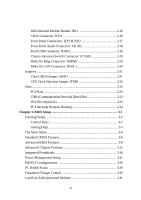
Features 3-6 Advanced BIOS Features 3-8 Advanced Chipset Features 3-12 Integrated Peripherals 3-16 Power Management Setup 3-21 PnP/PCI Configurations 3-26 PC Health Status 3-29 Frequency/Voltage Control 3-30 Load Fail-Safe/Optimized Defaults 3-31 Set Supervisor/User Password 3-32 - MSI MS 6378 | User Guide - Page 38
Chapter 3 Entering Setup Power on the computer and the system will start POST (Power On Self Test) process. When the message below appears on the screen, press key to enter Setup. Press DEL to enter SETUP If the message disappears before you respond and you still wish to enter Setup, restart - MSI MS 6378 | User Guide - Page 39
BIOS Setup Getting Help After entering the Setup menu, the first menu you will see a sub-menu. If you want to return to the main menu, just press . General Help The BIOS setup program provides a General Help screen. You can call up this screen from any menu by simply pressing . The - MSI MS 6378 | User Guide - Page 40
8PC Health Status 8Frequency/Voltage Control Load Fail-Safe Defaults Load Optimized Defaults Set Supervisor Password Set User Password Save & Exit Setup Exit Without Saving ESC : Quit F9 : Menu in BIOS F10 : Save & Exit Setup Select Item Time, Date, Hard Disk Type... Standard CMOS - MSI MS 6378 | User Guide - Page 41
. Load Optimized Defaults Use this menu to load the BIOS default values that are factory settings for optimal system operations. Set Supervisor Password Use this menu to set Supervisor Password. Set User Password Use this menu to set User Password. Save & Exit Setup Save CMOS value changes to - MSI MS 6378 | User Guide - Page 42
month, year and century Video Halt On EGA/VGA All, But Keyboard Base Memory Extended Memory Total Memory 640K 65472K 66212K Move BIOS. Read-only. month The month from Jan. through Dec. date The date from 1 to 31 can be keyed by numeric function keys. year The year can by adjusted by users - MSI MS 6378 | User Guide - Page 43
type of floppy drives installed. Available options: None, 360K, 5.25 in., 1.2M, 5.25 in., 720K, 3.5 in., 1.44M, 3.5 in., 2. 88M, 3.5 in. Video The setting controls the type of video adapter used for the primary monitor of the system. Available options: EGA/VGA , CGA 40, CGA 80, MONO. Halt On The - MSI MS 6378 | User Guide - Page 44
into this area, BIOS will show a warning message on screen and alarm beep. OS Select for DRAM > 64MB Video BIOS Shadow C8000-CBFFF Shadow data into this area is made, BIOS will display a warning message on screen and beep. Settings: Disabled, Enabled. CPU Internal Cache/External Cache The items - MSI MS 6378 | User Guide - Page 45
BIOS Setup CPU L2 Cache ECC Checking This allows you to enable or disable the ECC (Error-Correcting Code) feature for error detection and correction when data passes through L2 cache memory. Settings: Enabled, Disabled. Quick Power On Self Test The option speeds up Power On Self Test (POST) after - MSI MS 6378 | User Guide - Page 46
of BIOS password protection that is implemented. Settings are described below: Option Setup Description The password prompt appears only when end users try design guide, the system is able to run in APIC mode. Enabling APIC mode will expand available IRQs resources for the system. Settings: - MSI MS 6378 | User Guide - Page 47
you to run the OS/2® operating system with DRAM greater than 64MB. Setting options: Non-OS2, OS2. Video BIOS Shadow This item sets if the Video BIOS will be copied to RAM and increase video speed accordingly. Settings: Enabled, Disabled. C8000-CBFFF/CC000-CFFFF/D0000-D3FFF/D4000-D7FFF/D8000-DBFFF - MSI MS 6378 | User Guide - Page 48
DRAM Timing by SPD x SDRAM Cycle Length x DRAM Clock Memory Hole P2C/C2P Concurrency Fast R-W Turn Around System BIOS Cacheable Video RAM Cacheable Frame Buffer Size AGP Aperture Size OnChip USB USB Keyboard Support OnChip Sound OnChip Modem CPU to PCI Write Buffer PCI Dynamic Bursting PCI Master - MSI MS 6378 | User Guide - Page 49
the best CAS latency length. DRAM Clock The chipset supports synchronous and asynchronous mode between host clock and DRAM clock frequency. Settings: Auto, 100, 133 (MHz). Auto allows BIOS to determine the best DRAM clock frequency. Memory Hole In order to improve performance, certain space in - MSI MS 6378 | User Guide - Page 50
you have USB peripherals. Settings: Enabled, Disabled. USB Keyboard Support Set to Enabled if your need to use a USB keyboard in the operating system that does not support or have any USB driver installed, such as DOS and SCO Unix. OnChip Sound Auto allows the mainboard to detect whether an audio - MSI MS 6378 | User Guide - Page 51
BIOS Setup PCI Master 0 WS Write When Enabled, writes to the PCI bus are executed with zero wait state. PCI Delay Transaction The chipset has an embedded 32-bit posted write buffer to support AGP read cycle. Memory Parity/ECC Check Users can set the field to Enabled for memory checking if the type - MSI MS 6378 | User Guide - Page 52
Primary Slave UDMA Secondary Master UDMA Secondary Slave UDMA Init Display First Onboard Lan Device IDE HDD Block Mode Onboard FDD Controller Onboard Serial Port 1 Onboard contains an IDE interface with support for two IDE channels. Choose Enabled to activate each channel separately. 3-16 - MSI MS 6378 | User Guide - Page 53
(Windows 95 OSR2 or a third-party IDE bus master driver). If your hard drive and your system software both support Ultra DMA/33, Ultra DMA/66 or even Ultra DMA/100, select Auto to enable BIOS support. Settings: Auto, Disable. Init Display First This item specifies which VGA card is your primary - MSI MS 6378 | User Guide - Page 54
(COM B). Selecting Auto allows BIOS to automatically determine the correct base I/O port address. Settings: Disabled, 3F8/IRQ4, 2F8 COM3 COM4 (I/O:3F8H) (I/O:3F8H) (I/O:3E8H) (I/O:2E8H) Onboard Serial port to be set at PORT1 IRQ ASSIGNED PORT2 IRQ ASSIGNED 9 9 99 DISABLED X DISABLED X 9 - MSI MS 6378 | User Guide - Page 55
Port ECP/EPP: Extended Capability Port + Enhanced Parallel Port ECP Mode Use DMA The ECP mode has to use the DMA channel, so after the user chooses the onboard parallel port with the ECP feature, the setting "ECP Mode Use 3-19 - MSI MS 6378 | User Guide - Page 56
with the EPP function, the setting "Parallel Port EPP Type" should be set. At this time either EPP1.7 spec or EPP1.9 spec can be chosen. Onboard Legacy Audio The item enables or disables the onboard audio features of the mainboard and the following audio options in the BIOS. Sound Blaster The item - MSI MS 6378 | User Guide - Page 57
BIOS Setup Power IPCA function 8Power Management ACPI Sleep Type PM Control by APM Video Off Option Video Off Method MODEM Use IRQ Soft-Off by PWRBTN State After ACPI-aware, such as Windows® 98SE/2000/ME, select Enabled. Settings: Enabled, Disabled. Power Management Press to enter the - MSI MS 6378 | User Guide - Page 58
Disable. User Define Allows end users to , all devices except CPU will be shut off. Settings: Disable, 1 Min CPU or chipset) is lost and hardware maintains all system context. S3(STR) The S3 sleep mode is a power-down state in which power is supplied only to essential components such as main memory - MSI MS 6378 | User Guide - Page 59
in memory will be used to restore the PC to the previous state when a "wake up" event occurs. PM Control by APM Setting to Yes will activate an Advanced Power Management (APM) device to enhance Max Saving mode and stop CPU internal clock. Settings: Yes, No. Video Off Option The settings are - MSI MS 6378 | User Guide - Page 60
occurs. Available settings are: On Reboots the computer. Off Leaves the computer in the power off state. Auto BIOS automatically determines the Note: To use the function of "Wake Up On LAN/Ring" , you need to install a modem/LAN card supporting power on function. RTC Alarm Resume The field is - MSI MS 6378 | User Guide - Page 61
BIOS Setup on a scheduled time/date. Date(of Month) The field specifies the date for RTC Alarm Resume. Settings: 0~31. Resume Time(hh:mm:ss) The field specifies the time for RTC Alarm system is ready, the system will interrupt itself and perform the service required by the I/O device. 3-25 - MSI MS 6378 | User Guide - Page 62
to operate at speeds nearing the speed the CPU itself uses when communicating with its own special only experienced users should make any changes to the default settings. CMOS by the PnP operating system like Windows® 98. When set to NO, BIOS will initialize all the PnP cards. So, select Yes - MSI MS 6378 | User Guide - Page 63
. The IRQ will be reserved for further request. PCI/VGA Palette Snoop When set to Enabled, multiple VGA devices operating on different buses can handle data from the CPU on each set of palette registers on every video device. Bit 5 of the command register in the PCI device configuration space is - MSI MS 6378 | User Guide - Page 64
Assign IRQ For VGA/USB Set to Enabled allows BIOS to assign an IRQ to VGA card/USB device. Choose Disabled if you want to release the IRQ. Assign IRQ For ACPI Selecting Auto allows BIOS to automatically assign an IRQ for SCI (System Control Interrupt) of ACPI spec. Settings: Auto, IRQ 9, IRQ 10 and - MSI MS 6378 | User Guide - Page 65
BIOS Setup PC Health Status This section shows the status of your system temperature, CPU core voltage, etc. Monitor function is available only if there is hardware monitoring mechanism onboard. CMOS Setup Utility - Copyright(C) 1984-2000 Award Software PC Health Status Current CPU Temp. Current - MSI MS 6378 | User Guide - Page 66
the clock generator's Spread Spectrum feature. Settings: Disabled, Enabled. Always disable the feature when overclocking the processor. CPU Host/PCI Clock This item specifies the clock frequency of CPU host bus (FSB) and PCI bus. It provides a method for end users to overclock the processor. If the - MSI MS 6378 | User Guide - Page 67
The two options on the main menu allow users to restore all of the BIOS settings to the default Fail-Safe or Optimized values. The Optimized Defaults are the default values set by the mainboard manufacturer specifically for optimal performance of the mainboard. The Fail-Safe Defaults are the default - MSI MS 6378 | User Guide - Page 68
Chapter 3 Set Supervisor/User Password When you select this function, a message as below will appear on the screen: Type the password, up to eight characters in length, and press . The password typed now will replace any previously set password from CMOS memory. You will be prompted to - MSI MS 6378 | User Guide - Page 69
2000 and Windows ME can fully support ACPI to allow users managing the system power flexibly. AGP main memory for high graphics quality and performance. ATX A modern shape and layout of mainboard OS and the components. The BIOS is stored in a ROM chip. Bus A set of hardware lines within the computer - MSI MS 6378 | User Guide - Page 70
CMOS memory to retain the date, time, and system setup parameters. COM In MS-DOS system, the name of a serial communications port. DOS supports four , DDR SDRAM, and RDRAM. For further instruction, please see the table below: Dynamic RAM (DRAM) Memory Technologies Type First Used FPM (60,70ns) - MSI MS 6378 | User Guide - Page 71
Memory (error correcting code memory) A type of memory known as FireWire or iLink, which supports data transfer rates of up to 400 anywhere on the LAN, so that many users can share expensive devices drivers. LPT (line printer terminal) Logical device name for a line printer; a name reserved by the MS - MSI MS 6378 | User Guide - Page 72
(Plug and Play) A set of specifications that allows a PC to configure itself automatically to work with peripherals. The user can "plug" in a peripheral device and "play" it without configuring the system manually. To implement this useful feature, both the BIOS that supports PnP and a PnP expansion
-
 1
1 -
 2
2 -
 3
3 -
 4
4 -
 5
5 -
 6
6 -
 7
7 -
8
-
9
-
10
-
11
-
12
-
13
-
14
-
15
-
16
-
17
-
18
-
19
-
20
-
21
-
22
-
23
-
24
-
25
-
26
-
27
-
28
-
29
-
30
-
31
-
32
-
33
-
34
-
35
-
36
-
37
-
38
-
39
-
40
-
41
-
42
-
43
-
44
-
45
-
46
-
47
-
48
-
49
-
50
-
51
-
52
-
53
-
54
-
55
-
56
-
57
-
58
-
59
-
60
-
61
-
62
-
63
-
64
-
65
-
66
-
67
-
68
-
69
-
70
-
71
-
72
 |
 |
i
Version 3.1
G52-MA00585
MS-6378 (v3.X) Micro-ATX Mainboard
MSI
MICRO-STAR INTERNATIONAL