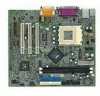
MSI MS 6378 User Guide - Page 28
IrDA Infrared Module Header: JIR1, CD-In Connector: JCD1
 |
View all MSI MS 6378 manuals
Add to My Manuals
Save this manual to your list of manuals |
Page 28 highlights
Chapter 2 IrDA Infrared Module Header: JIR1 The connector allows you to connect to IrDA Infrared module. You must configure the setting through the BIOS setup to use the IR function. JIR1 is compliant with Intel® Front Panel I/O Connectivity Design Guide. JIR1 Pin Definition Pin Signal 1 NC 2 NC 3 VCC 4 GND 5 IRTX 6 IRRX CD-In Connector: JCD1 JCD1 connector is for CD-ROM audio connector. JIR1 6 5 2 1 L GND R JCD1 2-16
-
 1
1 -
2
-
3
-
4
-
5
-
6
-
7
-
8
-
9
-
10
-
11
-
12
-
13
-
14
-
15
-
16
-
17
-
18
-
19
-
20
-
21
-
22
-
 23
23 -
 24
24 -
 25
25 -
 26
26 -
 27
27 -
 28
28 -
 29
29 -
 30
30 -
 31
31 -
 32
32 -
 33
33 -
34
-
35
-
36
-
37
-
38
-
39
-
40
-
41
-
42
-
43
-
44
-
45
-
46
-
47
-
48
-
49
-
50
-
51
-
52
-
53
-
54
-
55
-
56
-
57
-
58
-
59
-
60
-
61
-
62
-
63
-
64
-
65
-
66
-
67
-
68
-
69
-
70
-
71
-
72
 |
 |

Chapter 2
2-16
IrDA Infrared Module Header: JIR1
The connector allows you to connect to IrDA Infrared module.
You must
configure the setting through the BIOS setup to use the IR function.
JIR1 is
compliant with Intel
®
Front Panel I/O Connectivity Design Guide.
CD-In Connector: JCD1
JCD1 connector is for CD-ROM audio connector.
JCD1
GND
R
L
Pin
Signal
1
NC
2
NC
3
VCC
4
GND
5
IRTX
6
IRRX
JIR1 Pin Definition
JIR1
2
1
6
5