MSI MS 6378 User Guide - Page 19
Power Supply
 |
View all MSI MS 6378 manuals
Add to My Manuals
Save this manual to your list of manuals |
Page 19 highlights
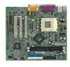
Hardware Setup Power Supply The mainboard supports ATX power supply for the power system. Before inserting the power supply connector, always make sure that all components are installed properly to ensure that no damage will be caused. ATX 20-Pin Power Connector: JPWR1 This connector allows you to connect to an ATX power supply. To connect to the ATX power supply, make sure the plug of the power supply is inserted in the proper orientation and the pins are aligned. Then push down the power supply firmly into the connector. 10 20 JPWR1 1 11 JPWR1 Pin Definition PIN SIGNAL 1 3.3V 2 3.3V 3 GND 4 5V 5 GND 6 5V 7 GND 8 PW_OK 9 5V_SB 10 12V PIN SIGNAL 11 3.3V 12 -12V 13 GND 14 PS_ON 15 GND 16 GND 17 GND 18 -5V 19 5V 20 5V 2-7
-
 1
1 -
2
-
3
-
4
-
5
-
6
-
7
-
8
-
9
-
10
-
11
-
12
-
13
-
 14
14 -
 15
15 -
 16
16 -
 17
17 -
 18
18 -
 19
19 -
 20
20 -
 21
21 -
 22
22 -
 23
23 -
 24
24 -
25
-
26
-
27
-
28
-
29
-
30
-
31
-
32
-
33
-
34
-
35
-
36
-
37
-
38
-
39
-
40
-
41
-
42
-
43
-
44
-
45
-
46
-
47
-
48
-
49
-
50
-
51
-
52
-
53
-
54
-
55
-
56
-
57
-
58
-
59
-
60
-
61
-
62
-
63
-
64
-
65
-
66
-
67
-
68
-
69
-
70
-
71
-
72
 |
 |

Hardware Setup
2-7
Power Supply
ATX 20-Pin Power Connector: JPWR1
This connector allows you to connect to an ATX power supply.
To
connect to the ATX power supply, make sure the plug of the power supply is
inserted in the proper orientation and the pins are aligned.
Then push down
the power supply firmly into the connector.
The mainboard supports ATX power supply for the power system.
Be-
fore inserting the power supply connector, always make sure that all compo-
nents are installed properly to ensure that no damage will be caused.
JPWR1
10
1
20
11
PIN
SIGNAL
11
3.3V
12
-12V
13
GND
14
PS_ON
15
GND
16
GND
17
GND
18
-5V
19
5V
20
5V
PIN
SIGNAL
1
3.3V
2
3.3V
3
GND
4
5V
5
GND
6
5V
7
GND
8
PW_OK
9
5V_SB
10
12V
JPWR1 Pin Definition