Mackie M1400/M1400i Owner's Manual - Page 12
METERS, Overload LED - specs
 |
View all Mackie M1400/M1400i manuals
Add to My Manuals
Save this manual to your list of manuals |
Page 12 highlights
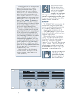
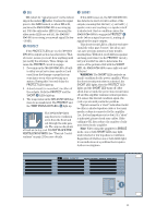
So what are the pros and cons of these two approaches? The reason some amplifier manufacturers use the constant gain approach is because the noise specification looks better. It's a fact of physics that as the gain of the amplifier increases, the circuit noise is amplified and increases too. By maintaining a constant gain, the noise spec for an 800W amplifier can look as good as the noise spec for a 100W amplifier. The downside to this is that you have to crank up your mixer level feeding the input of the amplifier, losing headroom and possibly increasing the noise level from the mixer (unless you have a Mackie mixer with low-noise VLZ circuitry!). Conversely, constant sensitivity demands that as the power increases, so must the gain. Yes, the output noise of the amplifier will increase, but you maintain the critical headroom available from your mixer. The additional noise is generally not a problem in live sound reinforcement situations. If it is, you can turn down the GAIN control a few clicks to find a happy compromise between noise floor and headroom available. As an added benefit, you can drive multiple amplifiers with the same signal and get the maximum power available from all of them. Mackie subscribes to the philosophy of constant sensitivity. Our amplifiers can be driven to full power with an input level of +4 dBu (1.23V rms). You may wonder why we didn't use just one stereo control to control both sides. That's in case your application requires a left/right imbalance (due to an irregularly shaped room) or if you're using the two sides for completely different purposes (monitor in channel 1 and side-fill in channel 2, for instance). Besides, they look cool. METERS The M•1400/M•1400i's meters indicate the relative output level of the amplifier referenced to full power. The numbers next to the meter's LEDs are in dB below full power. Ideally, the M•1400/M•1400i's -20, -9, -6, and -3 LEDs will flicker at normal signal levels, while the OL LED may flicker occasionally during peak moments. OL is short for Overload. Overloading, or clipping, occurs when the output voltage no longer linearly follows the input voltage and simply stops. This causes a sine wave to "square off," or get "clipped off." Thus, the term clipping. Fear not - this scenario is quite unlikely. Even with the GAIN controls fully up, the M•1400/M•1400i amplifier easily accepts professional "+4 dBu" operating levels. If the OL (Overload) LED is blinking frequently or continuously, turn down the source signal (i.e. the mixer's master faders). FULL SYMMETRY DUAL DIFFERENTIAL HIGH CURRENT DESIGN 12 00 00 CH 1 GAIN/dB 3v 18 20 22 2v 16 24 14 26 8 28 30 1v SENSITIVITY 1.23v (+4dBu) OL -3 -6 -9 -20 SIG OL -3 -6 -9 -20 SIG GAIN/dB CH 3v 18 20 22 2 2v 16 24 14 26 8 28 30 1v SENSITIVITY 1.23v (+4dBu) CH CH 1 2 INTERNAL STATUS PROTECT SHORT TEMP STATUS CH 1& 2 COLD HOT
-
 1
1 -
2
-
3
-
4
-
5
-
6
-
 7
7 -
 8
8 -
 9
9 -
 10
10 -
 11
11 -
 12
12 -
 13
13 -
 14
14 -
 15
15 -
 16
16 -
 17
17 -
18
-
19
-
20
-
21
-
22
-
23
-
24
-
25
-
26
-
27
-
28
-
29
-
30
-
31
-
32
 |
 |
