Mackie M1400/M1400i Owner's Manual - Page 15
POWER CORD, SPEAKER OUTPUTS, Bare Wire, Double Banana Plug, Spade Lug - hot
 |
View all Mackie M1400/M1400i manuals
Add to My Manuals
Save this manual to your list of manuals |
Page 15 highlights
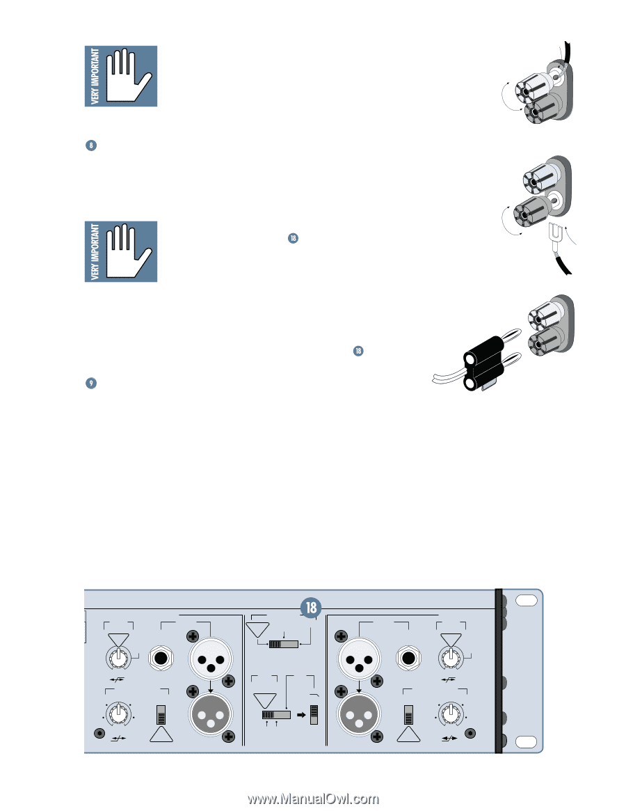
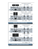
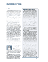
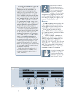
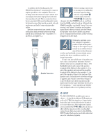
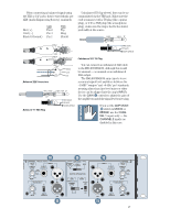
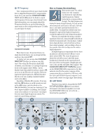
If you shut down your system, turn off your amplifiers first. When powering up, turn on your amplifiers last. This way, equipment feeding the amp won't "pop" or "thud" when it's powered up or down. POWER CORD We all know what a power cord is. The M•1400/M•1400i has a big beefy cord built in. Plug the power cord into an outlet that is capable of delivering the correct voltage for your model. For current-delivery purposes, the M•1400/ M•1400i's voltage source (wall outlet, extension cords, or power strips) must be capable of continuously delivering 15 amps (for 120V versions). And for safety reasons, that source must be a "3-prong" outlet with hot, neutral, and ground terminals. We're dealing with some big-time electricity here - don't mess with it. See "AC Power Considerations" on page 25 for more details. The red posts are labeled "+," which means positive. The black posts are labeled "-" for negative. You probably know the importance of getting these terms correct - if one side is hooked up "in phase" and the other side is "out of phase," you'll be "out of work." (By the way, although everyone says "phase" in this situation, the correct word is "polarity"... but it's not as much fun to say.) Using high-quality stranded speaker cable (16 gauge or thicker), connect the positive outputs of the M•1400/M•1400i to the positive inputs of your speakers, and the negative outputs to the negative inputs. The exception: If you're using the M•1400/M•1400i in BRIDGE mode, this does not apply, (see BRIDGE on page 22). In addition to the binding posts, the M•1400i also has 1/4" TS (tip-sleeve) SPEAKER OUTPUTS, so you can use speaker cables with 1/4" TS plugs. The tip is positive (+) and the shield is negative (-). They're wired in parallel with the binding posts and behave exactly the same (except they can't be used in BRIDGE mode). SPEAKER OUTPUTS Some call them "GR" jacks, others call them "Banana" jacks, but we prefer to call them "Binding Posts." You can call them whatever you like (except late for supper). These terminals are your standard fare. To use the binding post outputs, you can terminate your speaker cables with single or double banana plugs, spade lugs, or leave them unterminated: Unscrew the amp's binding posts enough to reveal the holes on their sides, then insert your stripped wires (stripped about 3/8" back) into the holes and retighten the posts (finger tight is fine - please don't reef on them with a wrench!). Be careful that no runaway strands touch the chassis or other terminals. G N D Bare Wire 1/4" Spade Lug Double Banana Plug 1 CHANNEL / BRIDGE / MONO LOW CUT INPUT FILTER TYPICAL 35 Hz BALANCED OR UNBALANCED STAGE MONITOR 100 Hz OFF 170 Hz CONSTANT DIRECTIVITY HORN EQ /AIR EQ 4.5 kHz ON 2k Hz 6k Hz AIR EQ OFF TYPICAL THRU AMP MODE STEREO MONO BRIDGE TYPICAL (CHS SUMMED) OUTPUT APPLICATION FULL RANGE LIMITER (CH1 & CH2) STEREO TYPICAL SUB WOOFER FREQUENCY 125Hz ON OFF 63Hz INPUT BALANCED OR UNBALANCED 2 CHANNEL LOW CUT FILTER TYPICAL 35 Hz STAGE MONITOR 100 Hz OFF 170 Hz CONSTANT DIRECTIVITY HORN EQ /AIR EQ ON 4.5k Hz THRU OFF TYPICAL 2k Hz 6k Hz AIR EQ 15
-
 1
1 -
2
-
3
-
4
-
5
-
6
-
7
-
8
-
9
-
 10
10 -
 11
11 -
 12
12 -
 13
13 -
 14
14 -
 15
15 -
 16
16 -
 17
17 -
 18
18 -
 19
19 -
 20
20 -
21
-
22
-
23
-
24
-
25
-
26
-
27
-
28
-
29
-
30
-
31
-
32
 |
 |