Mackie M1400/M1400i Owner's Manual - Page 22
Input, Power, Output, Application, Full Range, Limiter, Low Cut Filter, Speaker Output
 |
View all Mackie M1400/M1400i manuals
Add to My Manuals
Save this manual to your list of manuals |
Page 22 highlights
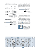
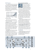
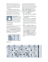
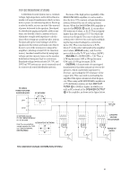
If you want to use a second M•1400/ M•1400i to reproduce the rest of the audio range, follow this procedure: 1. Connect the THRU jacks on the first subwoofer amplifier to the INPUT jacks on the second amplifier. 2. With POWER off, set the OUTPUT APPLICATION switch on the second amplifier to FULL RANGE (LIMITER either ON or OFF). 3. Set the LOW CUT FILTER frequency control to either 63Hz or 125Hz, depending on the cutoff frequency selected in the subwoofer amplifier . Since these exact frequencies are not labeled on the amplifier, you can guesstimate the position of the knob. 63Hz is located at about 1 o'clock and 125Hz is about 4 o'clock. If you want to be really accurate, you will need to use a variable-frequency signal generator along with a frequency counter and a voltmeter or oscilloscope to find the exact position for the knob. The voltmeter or o'scope should be capable of measuring low frequencies accurately (down to 60Hz). 1. Connect the signal generator to the INPUT of the amplifier and monitor the SPEAKER OUTPUT with the voltmeter or o'scope. 2. Adjust the signal generator level so you measure 1V rms output at 1kHz. (You should turn down the GAIN knobs on the amplifier about halfway.) 3. Change the frequency of the signal generator to 63Hz or 125Hz, whichever you're using as your subwoofer crossover frequency. You may need to use a frequency counter for accuracy. 4. Adjust the LOW CUT FILTER frequency control until the voltmeter or o'scope reads 0.707VAC rms. This is the -3 dB point, and means you have now matched the LOW CUT FILTER frequency cut-off point to the SUBWOOFER FREQUENCY switch setting (either 63Hz or 125Hz). After you've completed this exercise, you should mark the position of the control with a stick-on arrow or label so you don't have to repeat it should the control accidentally get moved. 22
-
 1
1 -
2
-
3
-
4
-
5
-
6
-
7
-
8
-
9
-
10
-
11
-
12
-
13
-
14
-
15
-
16
-
 17
17 -
 18
18 -
 19
19 -
 20
20 -
 21
21 -
 22
22 -
 23
23 -
 24
24 -
 25
25 -
 26
26 -
 27
27 -
28
-
29
-
30
-
31
-
32
 |
 |
