Mackie M1400/M1400i Owner's Manual - Page 4
Read - amp
 |
View all Mackie M1400/M1400i manuals
Add to My Manuals
Save this manual to your list of manuals |
Page 4 highlights
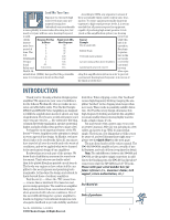
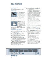
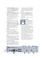
READ THIS PAGE! QUICK START I got ants in my pants and I got to dance! INSTALLATION The M•1400/M•1400i amp can be mounted in any standard rack system (see page 23), or placed horizontally on a floor or table. The heavier internal components are located towards the front of the chassis to make it easier to hold the amp by its front handles. IMPORTANT: The amplifier draws its ventilation air in from the front and out through the side panels. It needs plenty of fresh air to stay cool. DO NOT BLOCK THE VENTILATION PORTS (see page 23). CONNECTIONS AND SETTINGS 1. Be sure the POWER switch is off before making connections. 2. Turn the GAIN controls fully down (counterclockwise) for now. 3. Set both LOW CUT FILTER controls to their TYPICAL marks (35Hz). 4. Set both CONSTANT DIRECTIVITY switches OFF (unless you're using constant directivity horns with compression drivers). 5. Set the LIMITER switch on. Note: If you're using the M•1400/M•1400i to power a subwoofer, you probably do not need an external crossover. Please see SUBWOOFER on page 21 for details. 6. Determine which AMP MODE is best for your application: • STEREO mode (separate left and right inputs, separate left and right outputs) is the typical setup for amplifying stereo signals. • MONO mode (sometimes called DualMono mode - one mono input, two mono outputs) is for sending a mono signal to two different speaker sets, with separatelyadjustable level controls. • BRIDGE mode (sometimes called Bridged-Mono - one mono input, one mono output) uses both sides of the amp to double the power to one speaker set. An M•1400/M•1400i power amplifier, set to BRIDGE mode, delivers 1400 watts (into 4 ohms). Garsh! Note: 4 ohms is the minimum impedance you should connect to the amplifier in BRIDGE mode. If you connect a lower impedance load in BRIDGE mode, the SHORT LEDs may light, putting the amplifier into PROTECT mode. Set the AMP MODE switch accordingly. 7. In STEREO mode, connect line-level cables from your signal source to the M•1400/ M•1400i's INPUT jacks, either XLR or TRS: • The XLR and TRS inputs for each channel are wired in parallel. • The balanced XLR inputs are wired pin 2 = hot (+), pin 3 = cold (-) and pin 1 = shield (ground). • The 1/4" TRS inputs are wired tip = hot (+), ring = cold (-) and sleeve = shield (ground), and can accept either balanced (TRS) or unbalanced (TS) cables. FULL SYMMETRY DUAL DIFFERENTIAL HIGH CURRENT DESIGN 00 00 CH 1 GAIN/dB 3v 18 20 22 2v 16 24 14 26 8 28 30 1v SENSITIVITY 1.23v (+4dBu) OL -3 -6 -9 -20 SIG OL -3 -6 -9 -20 SIG GAIN/dB CH 3v 18 20 22 2 2v 16 24 14 26 8 28 30 1v SENSITIVITY 1.23v (+4dBu) CH CH 1 2 INTERNAL STATUS PROTECT SHORT TEMP STATUS CH 1& 2 COLD HOT 4 PROFESSIONAL POWER AMPLIFIER ON OFF POWER
-
 1
1 -
 2
2 -
 3
3 -
 4
4 -
 5
5 -
 6
6 -
 7
7 -
 8
8 -
 9
9 -
 10
10 -
11
-
12
-
13
-
14
-
15
-
16
-
17
-
18
-
19
-
20
-
21
-
22
-
23
-
24
-
25
-
26
-
27
-
28
-
29
-
30
-
31
-
32
 |
 |