Mackie M1400/M1400i Owner's Manual - Page 28
APPENDIX B: Technical Info, SPECIFICATIONS M•1400/M•1400i
 |
View all Mackie M1400/M1400i manuals
Add to My Manuals
Save this manual to your list of manuals |
Page 28 highlights
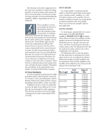
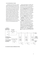
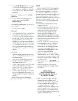
APPENDIX B: Technical Info SPECIFICATIONS M•1400/M•1400i Continuous Average Output Power, both channels driven: 250 watts per channel into 8 ohms from 20Hz to 20kHz, with no more than 0.012% THD 425 watts per channel into 4 ohms from 20Hz to 20kHz, with no more than 0.025% THD 630 watts per channel into 2 ohms from 20Hz to 20kHz, with no more than 0.050% THD Bridged mono operation: 850 watts into 8 ohms from 20Hz to 20kHz, with no more than 0.025% THD 1260 watts into 4 ohms from 20Hz to 20kHz, with no more than 0.050% THD Maximum Power at 1% THD: 300 watts per channel into 8 ohms 500 watts per channel into 4 ohms 700 watts per channel into 2 ohms 1000 watts into 8 ohms bridged 1400 watts into 4 ohms bridged Note: Power ratings are specified at 120VAC (U.S. and Canada) and 240VAC (Export) line voltages. The M•1400/M•1400i power amplifier draws large amounts of current from the AC line with continuous sine wave testing. Accurate measurement of power requires a steady and stable AC supply. This means the line impedance must be very low to insure that the peak AC line voltage does not sag to less than 97% of its value. If driving highly reactive loads, we recommend that the limiter circuit be engaged. Power Bandwidth: 20Hz to 70kHz (+0, -3 dB) Frequency Response: 20Hz to 40kHz (+0, -1 dB) 10Hz to 70kHz (+0, -3 dB) Distortion: THD, SMPTE IMD, TIM < 0.025% @ 8Ω < 0.050% @ 4Ω < 0.150% @ 2Ω Signal-to-Noise Ratio: > 107 dB below rated power into 4 ohms Channel Separation: > 80 dB @ 1kHz Damping Factor: > 350 from 0 to 400Hz Input Impedance: 20kΩ balanced bridging Input Sensitivity: 1.23 volts (+4 dBu) for rated power into 4 ohms Gain: 30.25 dB (32.5V/V) Maximum Input Level: 9.75 volts (+22 dBu) Rise Time: < 4.4µs Slew Rate: Voltage Slew Rate > 50V/µs > 100V/µs bridged Current Slew Rate > 32A/µs at 2Ω CMRR: > 40 dB, 20Hz to 20kHz Load Angle: 8(±jx) time independent at 8Ω 4(±jx) time dependent, T > 6 min. at 4Ω 2(1±jx) time dependent, T > 2 min. at 2Ω Transient Recovery: < 1µs for 20 dB overdrive @ 1kHz High Frequency Overload and Latching: No latch up at any frequency or level. High Frequency Stability: Unconditionally stable driving any reactive or capacitive load. Turn On Delay: 3 seconds Variable Low-Cut Filter: 10Hz (Off) to 170Hz, 2nd Order Bessel Subwoofer Low-Pass Filter: Switched: 63Hz/125Hz, 3rd Order Bessel Constant Directivity High Frequency Boost: 2kHz to 6kHz (+3 dB points) 6 dB/octave high-frequency shelving filter, (shelving occurs at approximately 30kHz) Limiter Section: Complementary Positive and Negative Peak Detecting 28
-
 1
1 -
2
-
3
-
4
-
5
-
6
-
7
-
8
-
9
-
10
-
11
-
12
-
13
-
14
-
15
-
16
-
17
-
18
-
19
-
20
-
21
-
22
-
 23
23 -
 24
24 -
 25
25 -
 26
26 -
 27
27 -
 28
28 -
 29
29 -
 30
30 -
 31
31 -
 32
32
 |
 |