Mackie M1400/M1400i Owner's Manual - Page 20
Bridge, Output Application, Limiter, Limiter On Typical
 |
View all Mackie M1400/M1400i manuals
Add to My Manuals
Save this manual to your list of manuals |
Page 20 highlights
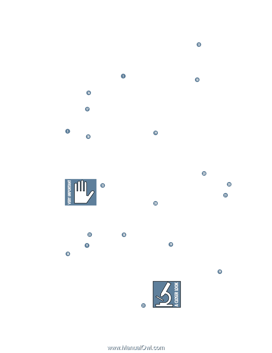
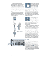
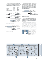
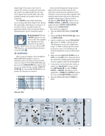
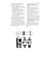
The AMP MODE switch determines the input signal routing within the M•1400/M•1400i amplifier. Shipped from the factory, the switch is set to STEREO. This is correct for about 90% of the applications using an amp like this (hence the TYPICAL indicator near it). But you may be in the 10% bracket, requiring special input routing within the amp. AMP MODE should be configured before operation - if you must change it during performance, turn down the GAIN controls as a precaution to protect the speakers from any inadvertent pops or thumps. STEREO mode (separate left and right inputs, separate left and right outputs) is the typical setup for amplifying stereo signals. MONO mode (sometimes called DualMono - one mono input, two mono outputs) is for sending a mono signal to two different speaker sets, with separately-adjustable GAIN controls. BRIDGE mode (sometimes called Bridged-Mono - one mono input, one mono output) uses both sides of the amp to double the power to one speaker set. With two M•1400/M•1400i power amplifiers, each set to BRIDGE mode, you can deliver as much as 1400 watts per amplifier. If you set the AMP MODE switch to MONO or BRIDGE, use the CHANNEL 1 inputs only - the CHANNEL 2 inputs go nowhere in this case. Note: There is one exception to this rule. If you have the OUTPUT APPLICATION switched to SUBWOOFER, the inputs to Channels 1 and 2 are summed regardless of the AMP MODE setting (see ). Also, BRIDGE mode requires special connections at the SPEAKER OUTPUTS . BRIDGE In STEREO mode, the M•1400/M•1400i Power Amplifier can deliver 700 watts per side into 2 ohms. If that's not enough, you can use two M•1400/M•1400i's, each in BRIDGE mode, and deliver 1400 watts per amplifier into 4 ohms. Or, you can use one amp in BRIDGE mode to power a monaural system. Finally, BRIDGE mode is also popular for subwoofer applications - but please see SUBWOOFER on the next page for a special subwoofer surprise. To use all the M•1400/M•1400i's power to drive one speaker cabinet using BRIDGE mode, you'll have to do four things: 1. Turn off the power to the M•1400/M•1400i. 2. Set the AMP MODE switch to BRIDGE. 3. Connect the positive side of the speaker cable to the Channel 1 red (+) binding post. 4. Connect the negative side of the speaker cable to the Channel 2 red (+) binding post. 5. (Okay, make that five things!) Use only the CHANNEL 1 INPUT (unless you're using the SUBWOOFER OUTPUT APPLICATION). The CHANNEL 1 GAIN control adjusts the output level of the amplifier. The CHANNEL 2 GAIN control has no effect. Once again: Before making connections to an amp or reconfiguring an amp's routing, turn the power off, make the changes, then turn the power back on. OUTPUT APPLICATION The OUTPUT APPLICATION switch should be configured before you turn on the amplifier. This switch allows you to choose between three different configurations: LIMITER ON (TYPICAL). This is the normal configuration: full-bandwidth audio with protective limiting (please see ). LIMITER OFF is also full bandwidth audio, but without protective limiting (please see ). SUBWOOFER mode, with built-in low-pass filter, no protective limiting (please see ). LIMITER The LIMITER is not designed to alter your sound - it's just there to protect your speakers from clipping. Its effect is virtually transparent, meaning you probably won't even notice any audible difference. We recommend that you leave it engaged (via OUTPUT APPLICATION ), hence the TYPICAL label below it. If you're working at quiet levels all the time, or you've already placed a compressor/limiter in the signal path, or if you just hate compression, you can leave the LIMITER out of the circuit (via OUTPUT APPLICATION ). The LIMITER is channel independent; that is, it works independently on each channel. It senses when the amplifier channel is about to be overdriven and attenuates the overall level just enough to keep the signal from clipping. Clipping occurs when the output voltage no longer linearly follows the input voltage and 20
-
 1
1 -
2
-
3
-
4
-
5
-
6
-
7
-
8
-
9
-
10
-
11
-
12
-
13
-
14
-
 15
15 -
 16
16 -
 17
17 -
 18
18 -
 19
19 -
 20
20 -
 21
21 -
 22
22 -
 23
23 -
 24
24 -
 25
25 -
26
-
27
-
28
-
29
-
30
-
31
-
32
 |
 |