Mackie M1400/M1400i Owner's Manual - Page 18
Thru, Low Cut Filter, Constant Directivity, Warning
 |
View all Mackie M1400/M1400i manuals
Add to My Manuals
Save this manual to your list of manuals |
Page 18 highlights
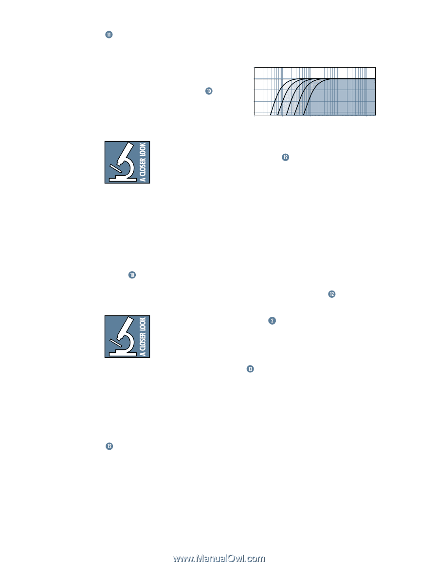
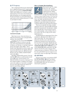
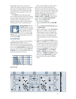
THRU Someday you'll do a show at Carnegie Hall and realize that one M•1400/M•1400i amplifier is just not going to do the job - you'll need a six-foot-high rack full of 'em. That's what the THRU jack is for. Simply plug the signal source outputs into the first amp's INPUTs , patch from that amp's THRU jacks to the next amp's INPUTs, and so on, daisy-chaining as many amps as you can afford (assuming your console has low-impedance outputs). A general rule of thumb is to maintain a load impedance 10 times or more than the source impedance to prevent excessive loading. If your console has an output impedance of 100 ohms, then you can daisy-chain up to twenty M•1400/ M•1400i amplifiers, which presents a load of 1000 ohms to the console (input impedance of 20 kohms divided by 20 amplifiers = 1000 ohms). The THRU jacks can also be used to relay the signal on to other devices such as a DAT or cassette recorder, enabling you to record exactly what the audience is hearing. The THRU jacks are wired straight from the XLR and TRS INPUTs - there is no electronic circuitry between - so the signal going into the amp is exactly the same as the signal coming out of the THRU jacks. You can use the THRU jack as an input, if necessary, since it's wired in parallel with the other input connectors. You can also use the 1/4" TRS INPUT jacks as THRU jacks. Simply connect the 1/4" TRS INPUT jacks on the first amplifier to the TRS 1/4" INPUT jacks on the second amplifier using 3-conductor shielded cables with TRS plugs on both ends. Warning: If you use a regular guitar cord with 2-conductor TS plugs, you'll unbalance the signal at the XLR input by grounding the low side (-) of the signal (pin 3). LOW CUT FILTER Every woofer has frequency response specifications. It's usually expressed in Hertz (or cycles per second), like "40Hz-300Hz." The "40Hz" refers to the low-frequency point (usually, but not always) where the speaker's output drops by 3 dB, and will "roll off" completely as the frequency goes down. There is no point in sending a woofer any frequencies it can't reproduce - you can't hear it, and worse yet, it's a waste of amplifier power that can be better used reproducing frequencies you can hear. 5dB 0dB -5dB -10dB -15dB Low1Hz Cut Filter10FHz requency100RHz esponse 1kHz 10kHz 20kHz In order to match the output bandwidth with your particular speaker system, the M•1400/M•1400i amplifier has a tunable LOW CUT FILTER . The frequencies are clearly marked along the knob's travel : • Fully counterclockwise, the frequency is below 10Hz, effectively bypassing the filter. • Center detent is 35Hz and labeled TYPICAL, since precious few woofers actually go below that. • 3/4 of the way up is labeled STAGE MONITOR, 100Hz, perfect for, well, stage monitors (they seldom reproduce below 100Hz; besides, it prevents low-frequency "leakage" into the house). • Fully clockwise is labeled 170Hz. So, grab your woofer's spec sheet and find the low roll-off spec. Then set the M•1400/ M•1400i's LOW CUT FILTER at the same frequency. If you do this correctly (and make sure the meters are happy), you'll never again see your woofer moving sporadically without audible signal. Your system will play louder and cleaner, and you may never blow another woofer again! CONSTANT DIRECTIVITY Compression drivers mounted on constantdirectivity horns require compensation, in the form of a high-frequency boost, with its "knee" set somewhere between 2kHz and 6kHz. Until now, you'd have to resort to external crossovers or worse yet, graphic EQ modules. Both of these are fraught with limitations, not to mention adding cost, rack space requirements and complexity to your system. The M•1400/M•1400i Power Amplifier eliminates the need for any of these external devices - they have the compensation circuitry already built in. And using it is a breeze. 18
-
 1
1 -
2
-
3
-
4
-
5
-
6
-
7
-
8
-
9
-
10
-
11
-
12
-
 13
13 -
 14
14 -
 15
15 -
 16
16 -
 17
17 -
 18
18 -
 19
19 -
 20
20 -
 21
21 -
 22
22 -
 23
23 -
24
-
25
-
26
-
27
-
28
-
29
-
30
-
31
-
32
 |
 |