Makita RJ01W Technical Reference - Page 11
Circuit diagram Wiring diagram
 |
View all Makita RJ01W manuals
Add to My Manuals
Save this manual to your list of manuals |
Page 11 highlights
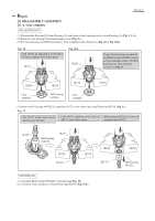
Circuit diagram Fig. D-1 Color index of lead wires' sheath Black Red White Terminal Switch B M1 M2 B Connector P 11/ 12 LED DC Motor Line filter unit (for the countries where suppression of Radio interference is regulated) Wiring diagram Fig. D-2 Wiring of LED Lead wire (Before setting DC Motor and Gear housing) Store the extra portion of Lead wires in this space designated with gray color. Do not put Lead wires on this Rib. Put the Lead wires between Boss B and Rib B. Fix the Lead wires in these Lead wire holders. Rib A Boss A Fix the Lead wires in these Lead wire holders. Tab Connector Rib B Boss B Fix the Lead wires in these Lead wire holders. Put the Lead wires between Rib A' s Tab and the wall of Housing (L), and pass them between Rib A and Boss A.
-
 1
1 -
2
-
3
-
4
-
5
-
 6
6 -
 7
7 -
 8
8 -
 9
9 -
 10
10 -
 11
11 -
 12
12
 |
 |
