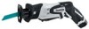
Makita RJ01W Technical Reference - Page 7
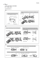
epair, 3] DISASSEMBLY/ASSEMBLY, 3] -3. Toolless Blade Holder Model JR100D
 |
View all Makita RJ01W manuals
Add to My Manuals
Save this manual to your list of manuals |
Page 7 highlights
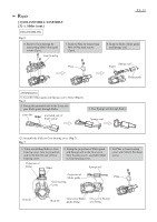
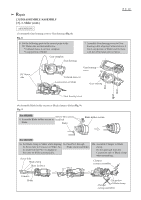
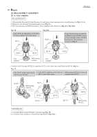
Repair P 7/ 12 [3] DISASSEMBLY/ASSEMBLY [3] -3. Toolless Blade Holder Section (Model JR100D) DISASSEMBLING (1) Disassemble Housing (R) from Housing (L) and remove Gear housing section from Housing (L) (Fig. 2, 3). (2) Remove Shoe from Gear section by unscrewing M4x10 Countersunk head screws (Fig. 3). (3) Disassemble Toolless blade holder section (Fig. 12). Fig. 12 1. Remove Protector and Retaining ring 16 by levering it up with Slotted screwdriver. 2. Remove Driving sleeve slowly, while paying attention that Shoulder pin is not slung by Compression spring 6. Remove Pin 3, Shoulder pin 5 and Compression spring 6 from Guide sleeve. Driving sleeve Pin 3 3. Remove Guide sleeve, Connecting sleeve, Push pin, Compression spring 2 and Torsion spring 17 from Blade guide. Connecting sleeve Retaining ring 16 Protector Compression spring 6 Shoulder pin 5 Torsion spring 17 Push pin Compression spring 2 Guide sleeve ASSEMBLING (1) Assemble Blade guide to Slider (Fig. 9) in case Blade guide is removed from Slider. (2) Mount Torsion spring 17 and Connecting sleeve to Blade guide. And then, inert Compression spring 2 and push pin (Fig. 13). Fig. 13 1. Assemble Torsion spring 17 to Blade guide by inserting its long tail into the slit of Blade guide. And insert the short tail of the Torsion spring into the hole of Connecting sleeve. 2. Insert Compression spring 2 and Push pin into the slit of Blade guide. Connecting sleeve short tail Torsion spring 17 long tail Blade guide Blade guide Connecting sleeve Push pin Compression spring 2
-
 1
1 -
 2
2 -
 3
3 -
 4
4 -
 5
5 -
 6
6 -
 7
7 -
 8
8 -
 9
9 -
 10
10 -
 11
11 -
 12
12
 |
 |
