Makita RJ01W Technical Reference - Page 5
Fig. 8, Fig. 9, For JR100D, For JR102D
 |
View all Makita RJ01W manuals
Add to My Manuals
Save this manual to your list of manuals |
Page 5 highlights
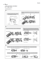
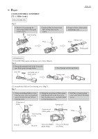
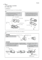
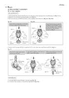
Repair [3] DISASSEMBLY/ASSEMBLY [3] -1. Slider (cont.) ASSEMBLING (3) Assemble Gear housing cover to Gear housing (Fig. 8). Fig. 8 6. Set the following parts to the nearest point to the DC Motor side as illustrated below. * Collared sleeve 4 on Gear complete * Loop portion of Slider Gear complete Gear housing P 5/ 12 7. Assemble Gear housing cover to Gear housing while aligning Collared sleeve 4 into Loop portion of Slider and fix them with 4x14 Pan head screws (3pcs). DC Motor side Gear housing cover Collared sleeve 4 Loop portion of Slider Gear housing Gear housing cover (4) Assemble Blade holder section or Blade clamp to Slider (Fig. 9). Fig. 9 For JR100D M3x12 Hex socket 8. Assemble Blade holder section to head bolt Slider. Slider Blade holder section. For JR102D 8a. Set Blade clamp to Slider while aligning its Screw hole to Concave on Slider. So, its small hole for Pin 3 is aligned to the same on Slider automatically. Screw hole Blade clamp Hole for Pin 3 9a. Pass Pin 3 through Blade clamp and Slider. Pin 3 10a. Assemble Clamper to Blade clamp. Do not approach from the Cut portion side of Blade clamp when assembling. Clamper (correct assemble) Concave Slider Cut portion of Blade clamp Clamper (wrong assemble)
-
 1
1 -
 2
2 -
 3
3 -
 4
4 -
 5
5 -
 6
6 -
 7
7 -
 8
8 -
 9
9 -
 10
10 -
 11
11 -
12
 |
 |
