Makita RJ01W Technical Reference - Page 8
] DISASSEMBLY/ASSEMBLY, 3] -3. Toolless Blade Holder Model JR100D cont., epair
 |
View all Makita RJ01W manuals
Add to My Manuals
Save this manual to your list of manuals |
Page 8 highlights
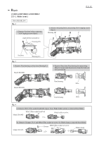
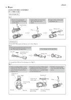
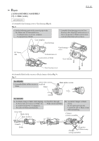
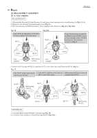
Repair [3] DISASSEMBLY/ASSEMBLY [3] -3. Toolless Blade Holder Section (Model JR100D) (cont.) P 8/ 12 ASSEMBLING (2) Do further step for Assembling in the order of Fig. 14, 15, 16, 17, 18. Fig. 14 3. Mount Guide sleeve to Blade guide. And align the holes each other for easy assembling of Shoulder pin 5 and Pin 3 in the next step. 4. Insert Compression spring 6 and Shoulder pin 5 into the large hole of Guide sleeve. Insert Pin 3 into the small hole of another side of Guide sleeve. Holes for Shoulder pin 5 Pin 3 Guide sleeve Guide sleeve Compression spring 6 Shoulder pin 5 Fig. 15 Slotted screwdriver Shoulder pin 5 Fig. 16 5. Press down Push pin with Slotted screwdriver till it stops while pushing Shoulder pin 5. Slotted screwdriver Pin 3 Guide sleeve Shoulder pin 5 Connecting sleeve Push pin Compression spring 2 Blade guide 6. And then, remove Slotted Screwdriver. So, Push pin is pushed back by Compression spring 2 and fits to Shoulder pin 5. Inner projection Driving sleeve 7. While pressing Shoulder pin 5, assemble Driving sleeve. Note; Locate this gray portion to Shoulder pin 5 and mount Driving sleeve to Guide sleeve. Note; These concaves on Connecting sleeve fit to the inner projection of Driving sleeve.
-
 1
1 -
2
-
 3
3 -
 4
4 -
 5
5 -
 6
6 -
 7
7 -
 8
8 -
 9
9 -
 10
10 -
 11
11 -
 12
12
 |
 |
