McAfee IIP-S14C-NA-100I Product Guide
McAfee IIP-S14C-NA-100I - IntruShield 1400 Sensor Appliance Manual
 |
View all McAfee IIP-S14C-NA-100I manuals
Add to My Manuals
Save this manual to your list of manuals |
McAfee IIP-S14C-NA-100I manual content summary:
- McAfee IIP-S14C-NA-100I | Product Guide - Page 1
IntruShield Sensor 1400 Product Guide revision 8.0 McAfee® IntruShield® IPS IntruShield Security Manager (ISM) version 4.1 McAfee® Network Protection Industry-leading intrusion prevention solutions - McAfee IIP-S14C-NA-100I | Product Guide - Page 2
Regents of the University of California, (C) 1990, 1993, with code derived from software contributed to Berkeley by Chris Torek. Issued MAY 2010 / IntruShield 1400 Product Guide 700-1545-00/ 8.0 - English - McAfee IIP-S14C-NA-100I | Product Guide - Page 3
Contents Preface ...iv Introducing McAfee IntruShield IPS iv About this guide...iv Contents of this guide ...iv Audience ...v Conventions used in this guide ...v Related Documentation...vi Contacting Technical Support ...vi Chapter 1 An introduction to IntruShield sensors 1 What is an IntruShield - McAfee IIP-S14C-NA-100I | Product Guide - Page 4
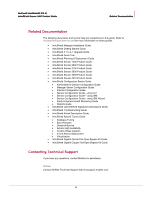
documents for this guide and how to contact McAfee Technical Support. Introducing McAfee IntruShield IPS McAfee IntruShield delivers the most comprehensive, accurate, and scalable network IPS solution for mission-critical enterprise, carrier, and service provider networks, while providing unmatched - McAfee IIP-S14C-NA-100I | Product Guide - Page 5
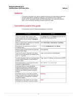
to perform particular tasks. Conventions used in this guide This document uses the following typographical conventions: Convention shown in Arial Narrow bold font. The Service field on the Properties tab specifies the name of the requested service. Menu or action group selections are indicated - McAfee IIP-S14C-NA-100I | Product Guide - Page 6
& System Health Monitoring Guide • Reports Guide • IntruShield User-Defined Signatures Developer's Guide • IntruShield Troubleshooting Guide • IntruShield Attack Description Guide • IntruShield Special Topics Guide • Database Tuning • Best Practices • Denial-of-Service • Sensor High Availability - McAfee IIP-S14C-NA-100I | Product Guide - Page 7
IntruShield® IPS 4.1 IntruShield Sensor 1400 Product Guide Contacting Technical Support Registered customers can obtain up-to-date Technical Support is available 7:00 A.M. to 5:00 P.M. PST Monday-Friday. Extended 24x7 Technical Support is available for customers with Gold or Platinum service - McAfee IIP-S14C-NA-100I | Product Guide - Page 8
- McAfee IIP-S14C-NA-100I | Product Guide - Page 9
and prevention of intrusions, misuse, and distributed denial of service (DDoS) attacks. IntruShield sensors are specifically designed to handle later chapters of this guide. The ISM server is described in detail in IntruShield Security Manager, Getting Started Guide. Sensor functionality The primary - McAfee IIP-S14C-NA-100I | Product Guide - Page 10
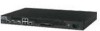
McAfee® IntruShield® IPS 4.1 IntruShield Sensor 1400 Product Guide An introduction to IntruShield sensors The IntruShield 1400 Sensor This document describes the I-1400 sensor. The IntruShield 1400 Sensor The IntruShield 1400 sensor (the I-1400) - McAfee IIP-S14C-NA-100I | Product Guide - Page 11
McAfee® IntruShield® IPS 4.1 IntruShield Sensor 1400 Product Guide An introduction to IntruShield sensors The IntruShield 1400 Sensor 8 Built-in internal tap (not shown). The internal tap (used with the 10/100 ports) provide - McAfee IIP-S14C-NA-100I | Product Guide - Page 12
McAfee® IntruShield® IPS 4.1 IntruShield Sensor 1400 Product Guide An introduction to IntruShield sensors The IntruShield 1400 Sensor LED Temp CardBus/PCMCIA 10/100 Monitoring Ports Speed 10/100 Monitoring Ports Link Response Port - McAfee IIP-S14C-NA-100I | Product Guide - Page 13
CHAPTER 2 Before you install Sensor specifications, safety measures, unpacking a sensor This chapter describes best practices for deployment of IntruShield sensors on your network. Topics include system requirements, site planning, safety considerations for handling the sensor, and usage - McAfee IIP-S14C-NA-100I | Product Guide - Page 14
Category 5 (Cat 5) OR Cat 5e cable can be used. Note: Throughout this guide, cabling specifications will be mentioned as Cat5/Cat5e. Sensor capacity for I-1400 sensor The Customized attacks Alert filters Default number of supported UDP Flows Supported UDP Flows 64 40,000 32,000 6,000 60,000 6 - McAfee IIP-S14C-NA-100I | Product Guide - Page 15
McAfee® IntruShield® IPS 4.1 IntruShield Sensor 1400 Product Guide Before you install Network topology considerations Maximum Type DoS Profiles SYN rate (64-byte packets network topology considerations for IntruShield deployment, see Pre-deployment considerations, Planning and Deployment Guide. 7 - McAfee IIP-S14C-NA-100I | Product Guide - Page 16
Sensor 1400 Product Guide Before you install qualified personnel should be allowed to install, replace, or service this equipment. • Before working on equipment that is connected not installed and used in accordance with the instruction manual, may cause harmful interference to radio communications. - McAfee IIP-S14C-NA-100I | Product Guide - Page 17
McAfee® IntruShield® IPS 4.1 IntruShield Sensor 1400 Product Guide Before you install Usage restrictions Usage restrictions The following restrictions apply to the use and operation the I-1200, four for the I-1400, six for the I-2600 and I-2700) • One printed Quick Start Guide • Release Notes 9 - McAfee IIP-S14C-NA-100I | Product Guide - Page 18
CHAPTER 3 Setting up the I-1400 sensor prior to configuration This chapter describes the process of setting up a sensor prior to configuring it via the ISM. Setup overview Setting up a sensor involves the following steps: 1 Positioning the sensor. (See Positioning the I-1400 (on page 10)) 2 - McAfee IIP-S14C-NA-100I | Product Guide - Page 19
McAfee® IntruShield® IPS 4.1 IntruShield Sensor 1400 Product Guide Setting up the I-1400 sensor prior to configuration Positioning the I-1400 2 Attach the first chassis ear to the right side of the chassis. Use a Phillips - McAfee IIP-S14C-NA-100I | Product Guide - Page 20
McAfee® IntruShield® IPS 4.1 IntruShield Sensor 1400 Product Guide Setting up the I-1400 sensor prior to configuration Cabling the sensor Figure 2: Mounting the I-1400 sensor in a rack Cabling the sensor Follow the steps outlined - McAfee IIP-S14C-NA-100I | Product Guide - Page 21
CHAPTER 4 Attaching cables to the I-1400 Sensor Follow the steps outlined in this chapter to connect cables to the various ports on your sensor. Cabling the Console port The Console port is used for setup and configuration of the sensor. 1 For console connections, plug the DB9 Console cable - McAfee IIP-S14C-NA-100I | Product Guide - Page 22
McAfee® IntruShield® IPS 4.1 IntruShield Sensor 1400 Product Guide Attaching cables to the I-1400 Sensor Cabling the Response ports Name Baud rate Number of bits Parity Stop bits Flow Control Setting 9600 8 None 1 None - McAfee IIP-S14C-NA-100I | Product Guide - Page 23
Product Guide Attaching cables to the I-1400 Sensor Cabling the Monitoring ports Cabling the Monitoring ports Monitoring ports connect to the network devices you will be monitoring via the sensor. You can deploy sensors in the operating modes shown in the following table. Cabling instructions for - McAfee IIP-S14C-NA-100I | Product Guide - Page 24
IntruShield® IPS 4.1 IntruShield Sensor 1400 Product Guide Attaching cables to the I-1400 Sensor Cabling Speed and Duplex are configurable Cable types for routers, switches, hubs, and PCs The cabling instructions in this chapter: • Use a crossover Ethernet RJ45 cable to connect a router port to - McAfee IIP-S14C-NA-100I | Product Guide - Page 25
McAfee® IntruShield® IPS 4.1 IntruShield Sensor 1400 Product Guide Cabling for in-line mode Attaching cables to the I-1400 Sensor Cabling for in-line mode Cabling the I-1400 to monitor in in-line mode - McAfee IIP-S14C-NA-100I | Product Guide - Page 26
McAfee® IntruShield® IPS 4.1 IntruShield Sensor 1400 Product Guide Attaching cables to the I-1400 Sensor Cabling for SPAN mode Note: The total cable length of the two LAN cables connected to the two ports - McAfee IIP-S14C-NA-100I | Product Guide - Page 27
IntruShield® IPS 4.1 IntruShield Sensor 1400 Product Guide Attaching cables to the I-1400 Sensor Cabling -closed mode, utilize the fail-closed dongles included with the product. TCP reset is not supported when connected in TAP mode. Cabling I-1400 sensors for failover The Response port is the - McAfee IIP-S14C-NA-100I | Product Guide - Page 28
3 A accomplishing fail-closed functionality 2 B boot LED 3 C cabling 13, 14, 15, 16, 18, 19 cabling for internal tap mode 19 cabling instructions 13 cabling the auxiliary port 14 cabling the console port 14 CardBus/PCMCIA port 2 CardBus/PCMCIA LED 3 configuration overview 11 connecting to - McAfee IIP-S14C-NA-100I | Product Guide - Page 29
T tap mode 19 Temp LED 3 U using fail-closed dongles - TAP mode 19 using peer ports 16
-
 1
1 -
 2
2 -
 3
3 -
 4
4 -
 5
5 -
 6
6 -
 7
7 -
8
-
9
-
10
-
11
-
12
-
13
-
14
-
15
-
16
-
17
-
18
-
19
-
20
-
21
-
22
-
23
-
24
-
25
-
26
-
27
-
28
-
29
 |
 |

IntruShield Sensor 1400 Product Guide
revision
8
.0
McAfee
®
Network Protection
Industry-leading intrusion prevention solutions
McAfee® IntruShield® IPS
IntruShield Security Manager (ISM)
version 4.1