McAfee IIP-S14C-NA-100I Product Guide - Page 26
► To connect the I-1400 sensor to the devices you want to monitor in internal tap mode:
 |
View all McAfee IIP-S14C-NA-100I manuals
Add to My Manuals
Save this manual to your list of manuals |
Page 26 highlights
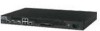
McAfee® IntruShield® IPS 4.1 IntruShield Sensor 1400 Product Guide Attaching cables to the I-1400 Sensor Cabling for SPAN mode Note: The total cable length of the two LAN cables connected to the two ports in Tap mode (that is 1A and 1B) cannot exceed 100 meters if you want to use failopen mode. Caution: As with cabling for in-line mode, cabling the sensor for internal tap mode requires a brief network interruption as you insert the sensor in the flow of network traffic. To avoid extended network downtime, you should cable the sensor for internal tap mode after you have completed all other configuration tasks. Note that the internal tap is designed with a mechanical loopback. When a sensor error or reboot takes place, a brief network interruption will occur as the two devices connected to the sensor establish connectivity. ► To connect the I-1400 sensor to the devices you want to monitor in internal tap mode: 1 For fail-open operation, plug a Cat 5/Cat 5e cable into port 1A. 2 Plug a Cat 5/Cat 5e cable into port 1B. Note: See Cable types for routers, switches, hubs, and PCs (on page 16) to determine which cable type to use with which type of network device. 3 Connect the other end of each cable to the network devices that you want to monitor. (For example, if you plan to monitor traffic between a switch and a router, connect the cable connected to 1A to the switch and the one connected to 1B to the router.) Cabling for SPAN mode Cabling the 1400 sensor to monitor in SPAN or hub mode When you monitor in SPAN or Hub mode, you do not need to use a port pair. You can use single ports. When you connect the 10/100 ports to SPAN or hub ports you must use a special fail-closed dongle that is supplied in the sensor box. ► To connect an I-1400 sensor to a SPAN port or Hub 1 Plug a Cat 5/ Cat 5e cable with the fail-closed dongle into one of the monitoring ports. 2 Connect the other end of the cable to the SPAN port or the hub. Note: See Cable types for routers, switches, hubs, and PCs (on page 16) to determine which cable type to use with which type of network device. 18
-
 1
1 -
2
-
3
-
4
-
5
-
6
-
7
-
8
-
9
-
10
-
11
-
12
-
13
-
14
-
15
-
16
-
17
-
18
-
19
-
20
-
 21
21 -
 22
22 -
 23
23 -
 24
24 -
 25
25 -
 26
26 -
 27
27 -
 28
28 -
 29
29
 |
 |
