McAfee IIP-S14C-NA-100I Product Guide - Page 18
Setting up the I-1400 sensor prior to configuration, Setup overview, Positioning the I-1400
 |
View all McAfee IIP-S14C-NA-100I manuals
Add to My Manuals
Save this manual to your list of manuals |
Page 18 highlights
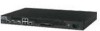
CHAPTER 3 Setting up the I-1400 sensor prior to configuration This chapter describes the process of setting up a sensor prior to configuring it via the ISM. Setup overview Setting up a sensor involves the following steps: 1 Positioning the sensor. (See Positioning the I-1400 (on page 10)) 2 Attaching power, network, and monitoring cables. (See Attaching Cables to the I- 1400 Sensor (on page 12)) 3 Powering on the sensor. (See Powering on the sensor.) Once you have set up and powered on the sensor, you can proceed with configuration. Positioning the I-1400 Place the sensor in a physically secure location, close to the switches or routers it will be monitoring. Ideally, the sensor should be located within a standard communications rack. Note: The illustrations in this section show an I-1200 sensor. To mount the sensor in a rack, you will attach two mounting ears to the sensor, then mount the ears to the rack. The sensor ears attach to either the front or the middle of the chassis. The I-1400 is 1RU (1 rack unit). Installing the ears on the chassis Caution: Before you install the ears on the chassis, make sure that power is OFF. Remove the power cable and all network interface cables from the sensor. Each rack-mounting ear has holes that match up with holes in the chassis. ► To install the ears on the chassis, follow these steps: 1 Verify that you have all the parts you will need: two chassis ears and twelve Phillips flathead screws. 10
-
 1
1 -
2
-
3
-
4
-
5
-
6
-
7
-
8
-
9
-
10
-
11
-
12
-
 13
13 -
 14
14 -
 15
15 -
 16
16 -
 17
17 -
 18
18 -
 19
19 -
 20
20 -
 21
21 -
 22
22 -
 23
23 -
24
-
25
-
26
-
27
-
28
-
29
 |
 |
