McAfee IIP-S14C-NA-100I Product Guide - Page 27
Cabling failover interconnection ports for 1400 sensor, Cabling I-1400 sensors for failover
 |
View all McAfee IIP-S14C-NA-100I manuals
Add to My Manuals
Save this manual to your list of manuals |
Page 27 highlights
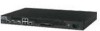
McAfee® IntruShield® IPS 4.1 IntruShield Sensor 1400 Product Guide Attaching cables to the I-1400 Sensor Cabling failover interconnection ports for 1400 sensor Cabling failover interconnection ports for 1400 sensor Failover requires connecting two identical I-1400 sensors (same model, same software) via an interconnection cable or cables. Previously, the creation of Sensor fail-over pair was allowed only if all the Primary sensor's monitoring port pairs were in in-line mode. Now, the flexibility to create a failover pair even if the Primary sensor has some of its monitoring port pairs in non-Inline (TAP/SPAN) mode, is provided. For example, in an I-1400, you may have port pairs 1A-1B configured in in-line mode and ports 2A-2B configured in SPAN mode. Note: When running the Sensor in in-line, fail-closed mode, utilize the fail-closed dongles included with the product. TCP reset is not supported when connected in TAP mode. Cabling I-1400 sensors for failover The Response port is the interconnection port on the I-1400. A crossover failover cable is the only additional hardware required to support failover communication between two I-1400 sensors. ► To connect two I-1400s for failover: 1 Plug a Cat 5/Cat 5e crossover cable into the Response port of the active sensor. 2 Connect the other end of the cable to the Response port of the standby sensor. Figure 4: Two I-1400s cabled for failover 19
-
 1
1 -
2
-
3
-
4
-
5
-
6
-
7
-
8
-
9
-
10
-
11
-
12
-
13
-
14
-
15
-
16
-
17
-
18
-
19
-
20
-
21
-
 22
22 -
 23
23 -
 24
24 -
 25
25 -
 26
26 -
 27
27 -
 28
28 -
 29
29
 |
 |
