McAfee IIP-S14C-NA-100I Product Guide - Page 23
Cabling the Monitoring ports, Using peer ports, Default monitoring port speed settings
 |
View all McAfee IIP-S14C-NA-100I manuals
Add to My Manuals
Save this manual to your list of manuals |
Page 23 highlights
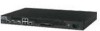
McAfee® IntruShield® IPS 4.1 IntruShield Sensor 1400 Product Guide Attaching cables to the I-1400 Sensor Cabling the Monitoring ports Cabling the Monitoring ports Monitoring ports connect to the network devices you will be monitoring via the sensor. You can deploy sensors in the operating modes shown in the following table. Cabling instructions for the sensor Monitoring ports are shown on the pages indicated. Cabling instructions for each monitoring mode: To cable the I-1400 in this mode... See... In-line mode Cabling the I-1400 to monitor in in-line mode (on page 17) Internal tap mode (10/100 ports) Cabling the I-1400 to monitor in internal Tap mode (on page 17) SPAN or Hub mode Cabling the I-1400 sensor to monitor in SPAN or hub mode Using peer ports All full-duplex sensor deployment modes require the use of two peer monitoring ports on the sensor. On the sensors, the numbered ports are wired in pairs to accommodate the traffic. The following ports are coupled and must be used together: 1A and 1B (10/100 ports) On the I-1400 Note: You cannot configure, for example, 1A and 2A to work together as a pair. Figure 3: Example port pair (peer ports) Default monitoring port speed settings Make sure that the switch/router ports connected to the sensor monitoring ports match the sensor configuration. 15
-
 1
1 -
2
-
3
-
4
-
5
-
6
-
7
-
8
-
9
-
10
-
11
-
12
-
13
-
14
-
15
-
16
-
17
-
 18
18 -
 19
19 -
 20
20 -
 21
21 -
 22
22 -
 23
23 -
 24
24 -
 25
25 -
 26
26 -
 27
27 -
 28
28 -
29
 |
 |
