Netgear EN516 EN516 Installation Guide
Netgear EN516 - Hub - EN Manual
 |
View all Netgear EN516 manuals
Add to My Manuals
Save this manual to your list of manuals |
Netgear EN516 manual content summary:
- Netgear EN516 | EN516 Installation Guide - Page 1
Installation Guide for the Model EN516 Ethernet Hub NETGEAR NETGEAR Inc. 4500 Great America Parkway Santa Clara, CA 95054 USA Phone: 1-888-NETGEAR E-mail: [email protected] www.NETGEAR.com M-EN516NA-1 September 2000 - Netgear EN516 | EN516 Installation Guide - Page 2
If it is not installed and used in accordance with the instruction manual, it may cause harmful interference to radio communications. Operation of Conformance This is to certify that the Bay Networks NETGEAR Model EN516 Ethernet Hub is shielded against the generation of radio interference in - Netgear EN516 | EN516 Installation Guide - Page 3
NETGEAR Model EN516 Ethernet Hub the notes in the operating instructions. Federal Office for problems, contact your point of purchase representative. To contact customer support or to purchase additional copies of this document and publications for other NETGEAR products, you can contact NETGEAR - Netgear EN516 | EN516 Installation Guide - Page 4
iv - Netgear EN516 | EN516 Installation Guide - Page 5
Tools ...3-2 Installing the Hub ...3-2 Installing the Hub on a Flat Surface 3-3 Installing the Hub in a Rack 3-3 Connecting the Hub ...3-4 Connecting to the RJ-45 Ports 3-4 Connecting to the BNC Port 3-7 Connecting to the AUI Port 3-9 Connecting to Other NETGEAR Products 3-10 Completing and - Netgear EN516 | EN516 Installation Guide - Page 6
Chapter 4 Troubleshooting Front Panel LEDs ...4-1 Collision LED ...4-1 Link/Rx LED for the RJ-45 Ports 4-2 AUI Rx LED and BNC Rx LED for the AUI and BNC Ports 4-2 Partition LED for the RJ-45 Ports 4-2 Partition LED for the BNC Port 4-2 Partition LED for the AUI Port 4-3 Installation ...4-3 - Netgear EN516 | EN516 Installation Guide - Page 7
port on the Model EN516 hub .....3-5 Cascading multiple hubs in a hierarchical star through the RJ-45 ports ..3-6 Cascading multiple hubs daisy-chain style through the RJ-45 ports .......3-7 Cascading hubs through the BNC port 3-8 Cascading hubs through the AUI port 3-9 Connecting multiple NETGEAR - Netgear EN516 | EN516 Installation Guide - Page 8
viii Figures - Netgear EN516 | EN516 Installation Guide - Page 9
Tables Table 2-1. LED descriptions 2-2 Table B-1. Table B-2. Table B-3. Electrical requirements of Category 3, 4, and 5 cables B-1 Specifications of 10BASE2 (ThinNet) RG 58 A/U or RG 58 C/U coaxial cable B-3 Specifications of AUI cable B-3 Table C-1. RJ-45 connector pin assignments C-2 Table - Netgear EN516 | EN516 Installation Guide - Page 10
- Netgear EN516 | EN516 Installation Guide - Page 11
purchase of the NETGEAR™ Model EN516 Ethernet Hub. The Model EN516 hub is part of the NETGEAR 500 Series product family, which delivers standards-based, plug-and-play networking solutions for small businesses, home offices, and low-density workgroups of larger companies. This guide describes how to - Netgear EN516 | EN516 Installation Guide - Page 12
Installation Guide for the Model EN516 Ethernet Hub • Built-in 100-240 V switching power supply, eliminating the need for bulky wall transformers • Thirty-eight front panel light emitting diode (LED) indicators, providing real-time status of the individual ports and overall hub status • Plug-and- - Netgear EN516 | EN516 Installation Guide - Page 13
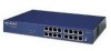
LEDs, 16 RJ-45 10BASE-T port connectors, and a Normal/Uplink push button (Figure 2-1). 1 2 16 PORT 10BASE-T Ethernet Hub BNC -45 ports with Link/Rx and Partition LEDs on each port 3 = Normal/Uplink push button Figure 2-1. Front panel of the Model EN516 hub 3 MODELEN516 8 Normal/Uplink 16 7432 - Netgear EN516 | EN516 Installation Guide - Page 14
Installation Guide for the Model EN516 Ethernet Hub LED Indicators There are six LEDs on the front panel of the hub and two on each port connector that allow you to identify: • Status of the hub AC power supply • Operational status of the hub • Collision occurrence on an Ethernet segment - Netgear EN516 | EN516 Installation Guide - Page 15
Installation Guide for the Model EN516 Ethernet Hub RJ-45 Ports The front panel of the Model EN516 hub provides 16 RJ-45 10BASE-T ports. Two LEDs, the Link/Rx LED and the Partition LED, are positioned at the top corners of each RJ-45 connector. Both LEDs are described - Netgear EN516 | EN516 Installation Guide - Page 16
Installation Guide for the Model EN516 Ethernet Hub Rear Panel The rear panel of the Model EN516 hub (refer to Figure 2-2) provides two ports, the AUI port and the BNC port. You can use the AUI port with the appropriate transceiver to connect the hub to a backbone network using thin coaxial cable, - Netgear EN516 | EN516 Installation Guide - Page 17
be connected are easily accessible for connecting cables and power and for monitoring the LED indicators. Package Contents The package should contain the following items: • Model EN516 hub • This manual Installation 3-1 - Netgear EN516 | EN516 Installation Guide - Page 18
Installation Guide for the Model EN516 Ethernet Hub • AC power cord • Rack mount kit • Hub To install the Model EN516 hub, follow these steps: 1. Unpack the hub. 2. Choose a location near the devices to be connected and close to an electrical outlet. 3. Follow the instructions for installing the hub - Netgear EN516 | EN516 Installation Guide - Page 19
Installation Guide for the Model EN516 Ethernet Hub Installing the Hub on a Flat Surface To install the hub on a flat surface such as a tabletop or shelf, follow these steps: 1. Install self-adhesive pads on the bottom of the hub. Peel off the protective backing from the rubber pads and apply one at - Netgear EN516 | EN516 Installation Guide - Page 20
to the AUI Port" on page 3-9 • "Connecting to Other NETGEAR Products" on page 3-10 Connecting to the RJ-45 Ports You can connect PCs, Apple Macintosh computers, UNIX workstations, and any device equipped with a 10BASE-T Ethernet interface to the RJ-45 ports on the Model EN516 hub using twisted pair - Netgear EN516 | EN516 Installation Guide - Page 21
Installation Guide for the Model EN516 Ethernet Hub Port 16 is switchable between Normal (MDI-X) and Uplink (MDI) positions and should be configured according to the following guidelines: • Set the Normal/Uplink push button - Netgear EN516 | EN516 Installation Guide - Page 22
Installation Guide for the Model EN516 Ethernet Hub Cascading refers to connecting hubs together to increase the number of ports, or the number of users supported on the network. The RJ-45, BNC, or AUI ports can be used to cascade hubs together. Figure 3-3 illustrates multiple hubs cascaded in a - Netgear EN516 | EN516 Installation Guide - Page 23
Installation Guide for the Model EN516 Ethernet Hub Figure 3-4 illustrates multiple hubs cascaded in a daisy-chain style. 1 Model EN516 hub 2 Model EN516 hub 3 Model EN516 hub 000029EA Key: 1 = Model EN516 hub with Normal/Uplink push button set to Normal position 2 and 3 = Model EN516 hub with - Netgear EN516 | EN516 Installation Guide - Page 24
Installation Guide for the Model EN516 Ethernet Hub 3. Connect the coaxial cable from another device that interconnection is not limited to hubs. 1 2 1 7217 Key: 1 = 50 Ω terminators 2 = BNC T-connector Figure 3-5. Cascading hubs through the BNC port Note: Ethernet specifications limit a BNC segment - Netgear EN516 | EN516 Installation Guide - Page 25
Installation Guide for the Model EN516 Ethernet Hub Connecting to the AUI Port The AUI port at the rear panel of the Model EN516 hub is normally used for connecting a thick coaxial segment. When using the AUI port, refer to Figure 3-6 and follow these steps: 1. Connect the AUI port on the hub to an - Netgear EN516 | EN516 Installation Guide - Page 26
Installation Guide for the Model EN516 Ethernet Hub Note: Ethernet specifications limit segments to 100 stations and 1,640 feet (500 m) in length, and specify that the AUI cable between the hub and the transceiver is limited to 164 feet (50 m). Connecting to Other NETGEAR Products You can extend - Netgear EN516 | EN516 Installation Guide - Page 27
Installation Guide for the Model EN516 Ethernet Hub Completing and Verifying the Installation To complete the installation, connect the power cord first to the power entry receptacle on the hub rear panel and then to the power outlet on the wall. When power has been applied to the hub, the following - Netgear EN516 | EN516 Installation Guide - Page 28
- Netgear EN516 | EN516 Installation Guide - Page 29
troubleshooting the Model EN516 hub. Front Panel LEDs The Model EN516 hub provides 38 front panel LEDs for monitoring individual ports and hub status. The power LED indicates when power is supplied to the hub. The following sections describe the LEDs that are used for monitoring the Model EN516 hub - Netgear EN516 | EN516 Installation Guide - Page 30
Installation Guide for the Model EN516 Ethernet Hub • Defective connectors are being used. For further information on pin assignment and cable specifications, refer to Appendix B, "Cabling Specifications," and Appendix C, "Connector Pin Assignments." Link/Rx LED for the RJ-45 Ports The green Link/Rx - Netgear EN516 | EN516 Installation Guide - Page 31
Installation Guide for the Model EN516 Ethernet Hub • Disconnected point somewhere along the terminate both ends with 50 Ω terminators. Partition LED for the AUI Port When the AUI port is connected with a 10BASE-T twisted pair or 10BASE-FL fiber optic B, "Cabling Specifications." Troubleshooting 4-3 - Netgear EN516 | EN516 Installation Guide - Page 32
Installation Guide for the Model EN516 Ethernet Hub Network Interface Cards Make sure the network interface cards installed in the workstations are in working condition. Configuration If problems occur after altering the network configuration, restore the original connections and determine the problem - Netgear EN516 | EN516 Installation Guide - Page 33
cations for the NETGEAR Model EN516 Ethernet Hub. General Specifications Network Protocol and Standards Compatibility IEEE 802.3 10BASE-T, 10BASE-2, 10BASE5 Ethernet IEEE 802.3 CSMA/CD Data Rate 10 Mbps, Manchester encoded Interface 16 10BASE-T ports (RJ-45) 1 BNC 10BASE-2 port 1 AUI port (15 pin - Netgear EN516 | EN516 Installation Guide - Page 34
Installation Guide for the Model EN516 Ethernet Hub Environmental Specifications Operating temperature: 0° C to 40° C (32° F to 104° F) Operating humidity: 90% maximum relative humidity commercial UL listed (UL 1950) CSA certified (CSA 22.2 #950) TUV licensed (EN 60 950) A-2 Technical Specifications - Netgear EN516 | EN516 Installation Guide - Page 35
Cabling Specifications This appendix provides specifications for cables used with the NETGEAR Model EN516 Ethernet Hub. Cable Specifications For 10 Mbps connections, Category 3, 4, or 5 cables can be used. NETGEAR highly recommends using Category 5 cable to avoid unnecessary expense or confusion if - Netgear EN516 | EN516 Installation Guide - Page 36
the Model EN516 Ethernet Hub Twisted Pair Cables For two devices to communicate, the transmitter of each device must be connected to the receiver of the other device. The crossover function is usually implemented internally as part of the circuitry in the device. Most repeaters and switch ports are - Netgear EN516 | EN516 Installation Guide - Page 37
Installation Guide for the Model EN516 Ethernet Hub 50 Ω Coaxial Cable . AUI Cable The AUI cable connects the AUI port on the Model EN516 hub to a transceiver. The Ethernet specifications limit the cable length to 164 ft - Netgear EN516 | EN516 Installation Guide - Page 38
- Netgear EN516 | EN516 Installation Guide - Page 39
appendix provides information on the RJ-45, AUI, and BNC connectors that are used for the NETGEAR Model EN516 Ethernet Hub. RJ-45 Connector The RJ-45 connector is used to connect workstations, hubs, and switches through unshielded twisted pair cable. The RJ-45 connector accepts four-pair Category - Netgear EN516 | EN516 Installation Guide - Page 40
Installation Guide for the Model EN516 Ethernet Hub Table C-1 lists the pin assignments for the RJ-45 connector. Table C-1. Pin 1 2 3 6 4, 5, 7, 8 RJ-45 connector pin assignments Normal assignment on ports 1 to 15 Input Receive Data + Input Receive Data Output Transmit Data + Output Transmit - Netgear EN516 | EN516 Installation Guide - Page 41
Installation Guide for the Model EN516 Ethernet Hub Table C-2 lists the AUI connector pin assignments. Table C-2. AUI mA maximum) BNC Connector The BNC connector for the Model EN516 hub supports 10 Mbps data transmission and connects the hub to other devices. Figure C-3 illustrates the parts of - Netgear EN516 | EN516 Installation Guide - Page 42
Installation Guide for the Model EN516 Ethernet Hub BNC T-Connector and 50 Ω Terminator The BNC port on the Model EN516 hub, with the BNC T-connector and the 50 Ω terminator, is used for connecting to a thin coaxial segment. Figure C-4 illustrates the BNC T-connector and 50 Ω terminator. For - Netgear EN516 | EN516 Installation Guide - Page 43
connector pin assignments (table) C-2 AUI Partition LED 2-2, 4-3 AUI port cascading hubs through 3-9 connecting to 3-9 description 2-4 AUI Rx LED 2-2, straight-through twisted pair 3-5, B-2 troubleshooting 4-3 cascading daisy-chain style 3-7 hierarchical star style 3-6 ports 3-4 to 3-9 Certificate of - Netgear EN516 | EN516 Installation Guide - Page 44
Installation Guide for the Model EN516 Ethernet Hub connector AUI pin assignments (table) C-2 BNC C-3 BNC-T C-4 RJ-45 pin assignments (table) C-1 crossover twisted pair cable B-2 customer support iii D daisy-chain cascade 3-7 F FCC statement ii features 1-1 front panel 2-1 H hierarchical star - Netgear EN516 | EN516 Installation Guide - Page 45
the Model EN516 Ethernet Hub P package contents 3-1 ports See also AUI See also BNC See also RJ-45 AUI 2-4 BNC 2-4 cascading 3-4 to 3-9 connecting 3-4 to 3-9 RJ-45 2-3 using transceivers to connect AUI 3-9 Power LED 2-2, 3-11, 4-1 T technical specifications A-1 technical support iii troubleshooting - Netgear EN516 | EN516 Installation Guide - Page 46
-
 1
1 -
 2
2 -
 3
3 -
 4
4 -
 5
5 -
 6
6 -
 7
7 -
8
-
9
-
10
-
11
-
12
-
13
-
14
-
15
-
16
-
17
-
18
-
19
-
20
-
21
-
22
-
23
-
24
-
25
-
26
-
27
-
28
-
29
-
30
-
31
-
32
-
33
-
34
-
35
-
36
-
37
-
38
-
39
-
40
-
41
-
42
-
43
-
44
-
45
-
46
 |
 |

M-EN516NA-1
September 2000
NETGEAR
NETGEAR Inc.
4500 Great America Parkway
Santa Clara, CA 95054
USA
Phone: 1-888-NETGEAR
E-mail: [email protected]
www.NETGEAR.com
Installation Guide
for the Model EN516
Ethernet Hub