Netgear EN516 EN516 Installation Guide - Page 44
RJ-45 Link/Rx
 |
View all Netgear EN516 manuals
Add to My Manuals
Save this manual to your list of manuals |
Page 44 highlights
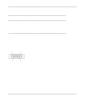
Installation Guide for the Model EN516 Ethernet Hub connector AUI pin assignments (table) C-2 BNC C-3 BNC-T C-4 RJ-45 pin assignments (table) C-1 crossover twisted pair cable B-2 customer support iii D daisy-chain cascade 3-7 F FCC statement ii features 1-1 front panel 2-1 H hierarchical star cascade 3-6 I installation cascading ports 3-4 to 3-9 completing 3-11 connecting ports 3-4 to 3-9 connecting to NETGEAR products 3-10 daisy-chain style 3-7 in a rack 3-3 network interface cards 4-4 on a flat surface 3-3 package contents 3-1 tools required 3-2 troubleshooting 4-3 verifying 3-11, 4-4 L LEDs AUI Partition 2-2, 4-3 AUI Rx 2-2, 4-2 BNC Partition 2-2, 3-11, 4-2 BNC Rx 2-2, 4-2 Collision 2-2, 4-1 description (table) 2-2 Power 2-2, 3-11, 4-1 RJ-45 Link/Rx 2-2, 3-11, 4-2 RJ-45 Partition 2-2 troubleshooting 4-1 M MDI device, setting Normal/Uplink push button 2-3 MDI port, connecting to B-2 MDI-X device, setting Normal/Uplink push button 2-3 MDI-X port, connecting to B-2 N network interface cards, troubleshooting 4-4 Normal/Uplink push button setting for MDI 2-3 setting for MDI-X 2-3 2 Index
-
 1
1 -
2
-
3
-
4
-
5
-
6
-
7
-
8
-
9
-
10
-
11
-
12
-
13
-
14
-
15
-
16
-
17
-
18
-
19
-
20
-
21
-
22
-
23
-
24
-
25
-
26
-
27
-
28
-
29
-
30
-
31
-
32
-
33
-
34
-
35
-
36
-
37
-
38
-
 39
39 -
 40
40 -
 41
41 -
 42
42 -
 43
43 -
 44
44 -
 45
45 -
 46
46
 |
 |
