Netgear EN516 EN516 Installation Guide - Page 14
LED Indicators
 |
View all Netgear EN516 manuals
Add to My Manuals
Save this manual to your list of manuals |
Page 14 highlights
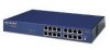
Installation Guide for the Model EN516 Ethernet Hub LED Indicators There are six LEDs on the front panel of the hub and two on each port connector that allow you to identify: • Status of the hub AC power supply • Operational status of the hub • Collision occurrence on an Ethernet segment indicating activity level • Partitioning of a port as a result of excessive collision occurrence • Data utilization of the Ethernet segment in a standalone hub or a stack of hubs • Link and receive activity status for all ports in the hub Table 2-1 describes each LED on the front panel of the hub. Table 2-1. Label Power BNC Rx AUI Rx Collision LED descriptions Color Green Green Green Yellow BNC Partition Yellow AUI Partition Link/Rx (located on top left corner of each RJ-45 port) Partition (located on top right corner of each RJ-45 port) Yellow Green Yellow Activity On Blinking Blinking Blinking On On On Blinking On Description Power is supplied to the hub. There is incoming data on the BNC port. There is incoming data on the AUI port. There is data collision on the network. Note that occasional collisions are normal. The BNC port is being partitioned because of excessive collisions, or when the BNC port is not connected. The AUI port is being partitioned because of excessive collisions. The link between this port and the other connecting port is good. There is incoming data on the port. The port is being partitioned because of excessive collisions. 2-2 Physical Description
-
 1
1 -
2
-
3
-
4
-
5
-
6
-
7
-
8
-
 9
9 -
 10
10 -
 11
11 -
 12
12 -
 13
13 -
 14
14 -
 15
15 -
 16
16 -
 17
17 -
 18
18 -
 19
19 -
20
-
21
-
22
-
23
-
24
-
25
-
26
-
27
-
28
-
29
-
30
-
31
-
32
-
33
-
34
-
35
-
36
-
37
-
38
-
39
-
40
-
41
-
42
-
43
-
44
-
45
-
46
 |
 |
