Netgear FSM726 FSM726 User Manual - Page 133
Normal Assignment On, Ports 1 To 8, Port 8, B-4
 |
UPC - 606449026856
View all Netgear FSM726 manuals
Add to My Manuals
Save this manual to your list of manuals |
Page 133 highlights
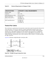
700 Series Managed Switch User's Guide for Software v2.1 Figure B-4 shows the RJ-45 plug and RJ-45 connector. Figure B-4: RJ-45 Plug and RJ-45 Connector with Built-in LEDs Table B-2 lists the pin assignments for the 10/100 Mbps RJ-45 plug and the RJ-45 connector. Table-B-2. 10/100 Mbps RJ-45 Plug and RJ-45 Connector Pin Assignments PIN 1 2 NORMAL ASSIGNMENT ON PORTS 1 TO 8 Input Receive Data + Input Receive Data - 3 Output Transmit Data + 6 Output Transmit Data - 4, 5, 7, 8 Internal termination, not used for data transmission UPLINK ASSIGNMENT ON PORT 8 Output Transmit Data + Output Transmit Data - Input Receive Data + Input Receive Data - Table E-2 lists the pin assignments for the 100/1000 Mbps RJ-45 plug and the RJ-45 connector. Cabling Guidelines B-7 SM-10004-02
-
 1
1 -
2
-
3
-
4
-
5
-
6
-
7
-
8
-
9
-
10
-
11
-
12
-
13
-
14
-
15
-
16
-
17
-
18
-
19
-
20
-
21
-
22
-
23
-
24
-
25
-
26
-
27
-
28
-
29
-
30
-
31
-
32
-
33
-
34
-
35
-
36
-
37
-
38
-
39
-
40
-
41
-
42
-
43
-
44
-
45
-
46
-
47
-
48
-
49
-
50
-
51
-
52
-
53
-
54
-
55
-
56
-
57
-
58
-
59
-
60
-
61
-
62
-
63
-
64
-
65
-
66
-
67
-
68
-
69
-
70
-
71
-
72
-
73
-
74
-
75
-
76
-
77
-
78
-
79
-
80
-
81
-
82
-
83
-
84
-
85
-
86
-
87
-
88
-
89
-
90
-
91
-
92
-
93
-
94
-
95
-
96
-
97
-
98
-
99
-
100
-
101
-
102
-
103
-
104
-
105
-
106
-
107
-
108
-
109
-
110
-
111
-
112
-
113
-
114
-
115
-
116
-
117
-
118
-
119
-
120
-
121
-
122
-
123
-
124
-
125
-
126
-
127
-
 128
128 -
 129
129 -
 130
130 -
 131
131 -
 132
132 -
 133
133 -
 134
134 -
 135
135 -
 136
136 -
 137
137 -
 138
138 -
139
-
140
-
141
-
142
-
143
-
144
-
145
-
146
-
147
-
148
-
149
-
150
-
151
-
152
 |
 |
