Netgear FSM726 FSM726 User Manual - Page 83
Advanced> Spanning Tree, Advanced> Spanning Tree >Bridge Settings
 |
UPC - 606449026856
View all Netgear FSM726 manuals
Add to My Manuals
Save this manual to your list of manuals |
Page 83 highlights
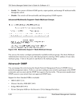
700 Series Managed Switch User's Guide for Software v2.1 Advanced> Spanning Tree This switch is compliant with IEEE802.1D Spanning Tree Protocol (STP). STP ensures that only one path at a time is active between any two network nodes. There maybe more than one physical path between any two nodes, forming a loop, either created for redundancy or by accident. STP ensures only one physical path is active and the others are blocked. If a loop is created for redundancy, STP will monitor the two paths and activate the stand-by path if the primary path fails. If a loop was created inadvertently, STP will disable one of the two paths. A loop in a network can disable your network by causing a "Broadcast storm", the result of a broadcast message traveling through the loop again and again. There are two sub-page of Spanning Tree configuration: • Bridge Settings • Port Settings Advanced> Spanning Tree >Bridge Settings Figure 5-34: Spanning Tree: Bridge Settings When Spanning tree is used in conjunction with a set of aggregated ports, also known as a port trunking, Spanning Tree will treat the trunk as a single virtual port. Spanning Tree can be enabled or disabled in this screen. Enable: There are four other tunable parameters to be addressed when enabled. Web-Based Management Interface SM-10004-02 5-33
-
 1
1 -
2
-
3
-
4
-
5
-
6
-
7
-
8
-
9
-
10
-
11
-
12
-
13
-
14
-
15
-
16
-
17
-
18
-
19
-
20
-
21
-
22
-
23
-
24
-
25
-
26
-
27
-
28
-
29
-
30
-
31
-
32
-
33
-
34
-
35
-
36
-
37
-
38
-
39
-
40
-
41
-
42
-
43
-
44
-
45
-
46
-
47
-
48
-
49
-
50
-
51
-
52
-
53
-
54
-
55
-
56
-
57
-
58
-
59
-
60
-
61
-
62
-
63
-
64
-
65
-
66
-
67
-
68
-
69
-
70
-
71
-
72
-
73
-
74
-
75
-
76
-
77
-
 78
78 -
 79
79 -
 80
80 -
 81
81 -
 82
82 -
 83
83 -
 84
84 -
 85
85 -
 86
86 -
 87
87 -
 88
88 -
89
-
90
-
91
-
92
-
93
-
94
-
95
-
96
-
97
-
98
-
99
-
100
-
101
-
102
-
103
-
104
-
105
-
106
-
107
-
108
-
109
-
110
-
111
-
112
-
113
-
114
-
115
-
116
-
117
-
118
-
119
-
120
-
121
-
122
-
123
-
124
-
125
-
126
-
127
-
128
-
129
-
130
-
131
-
132
-
133
-
134
-
135
-
136
-
137
-
138
-
139
-
140
-
141
-
142
-
143
-
144
-
145
-
146
-
147
-
148
-
149
-
150
-
151
-
152
 |
 |
