Nokia IP350 Installation Guide
Nokia IP350 - Security Appliance Manual
 |
View all Nokia IP350 manuals
Add to My Manuals
Save this manual to your list of manuals |
Nokia IP350 manual content summary:
- Nokia IP350 | Installation Guide - Page 1
60s and 100s Installation Guide Part No. N451545001 Rev A Published February 2005 - Nokia IP350 | Installation Guide - Page 2
States Government regarding its use, reproduction, and disclosure are as set forth in the Commercial Computer Software-Restricted Rights clause at FAR 52.227-19. IMPORTANT NOTE TO USERS This software and hardware is provided by Nokia Corporation as is and any express or implied warranties, including - Nokia IP350 | Installation Guide - Page 3
Site: Email: Americas Voice: Fax: Asia-Pacific Voice: Fax: https://support.nokia.com/ [email protected] Europe 1-888-361-5030 or 1-613-271-6721 Voice: 1-613-271-8782 Fax: +65-67232999 +65-67232897 +44 (0) 125-286-8900 +44 (0) 125-286-5666 021216 Nokia 60s and 100s Installation Guide 3 - Nokia IP350 | Installation Guide - Page 4
4 Nokia 60s and 100s Installation Guide - Nokia IP350 | Installation Guide - Page 5
12 Command-Line Conventions 13 Text Conventions 15 Related Documentation 16 1 Overview 17 About the Nokia 60s and 100s Appliances 17 Memory 17 Encryption Acceleration 18 Managing the Nokia 60s and 100s Appliances 18 Appliance Overview 19 Ethernet Management Ports 20 Built-in Console Port - Nokia IP350 | Installation Guide - Page 6
Interface Cards 47 Dual-Port 10/100 Ethernet Interface, PMC 47 Ethernet PMC NIC Features 48 Ethernet NIC Connectors and Cables 48 6 Installing and Replacing Other Components 51 Installing a PCMCIA Modem 52 Replacing a Hard-Disk Drive 53 Replacing or Upgrading Memory 57 Before You Start - Nokia IP350 | Installation Guide - Page 7
the System 79 Using the Boot Manager to Install IPSO 80 Protecting the Boot Manager with a Password 81 Installing the Boot Manager 81 Upgrading the Boot Manager 83 8 Troubleshooting 85 General Troubleshooting Information 85 Troubleshooting Routing Problems 95 A Technical Specifications 101 - Nokia IP350 | Installation Guide - Page 8
8 Nokia 60s and 100s Installation Guide - Nokia IP350 | Installation Guide - Page 9
35 Figure 11 Dual-Port Ethernet NIC Front Panel Details 48 Figure 12 Output Connector for the Ethernet Cable 49 Figure 13 Ethernet Crossover-Cable Pin Connections 50 Figure 14 Hard-Disk Drive Location 53 Figure 15 DIMM Socket Locations 58 Nokia 60s and 100s Appliance Installation Guide 9 - Nokia IP350 | Installation Guide - Page 10
10 Nokia 60s and 100s Appliance Installation Guide - Nokia IP350 | Installation Guide - Page 11
About this Guide This manual provides information for the installation and use of the Nokia 60s and 100s appliances. Installation and maintenance should be performed by experienced technicians or Nokia-approved service providers only. This preface provides the following information: „ In This Guide - Nokia IP350 | Installation Guide - Page 12
or replace PCMCIA modems, memory, the hard-disk drive, and an encryption accelerator card (Nokia 100s only). „ Chapter 7, "Using the Boot Manager" explains how to use the boot manager, which is part of the IPSO software. „ Chapter 8, "Troubleshooting" discusses problems you might encounter and - Nokia IP350 | Installation Guide - Page 13
performance, loss of data, or interruption of service. Note Notes provide information of special interest or recommendations. Command-Line Conventions This section defines the elements of commands that are available in Nokia Internet Communications products. You might encounter one or more of the - Nokia IP350 | Installation Guide - Page 14
slot 3 Separates alternative, mutually exclusive elements. framing To complete the command, supply the value. For example: framing sonet or framing sdh -flag A flag is usually the file. The extension might be optional in certain products. 14 Nokia 60s and 100s Installation Guide - Nokia IP350 | Installation Guide - Page 15
Indicates text you enter or type, for example: # configure nat Key names Keys that you press simultaneously are linked by a plus sign (+): Press Ctrl + Alt + Del. Menu commands Menu commands are separated by a greater than sign (>): Choose File > Open. Nokia 60s and 100s Installation Guide 15 - Nokia IP350 | Installation Guide - Page 16
You can find the Nokia 60s and 100s Installation Guide in PDF on the World Wide Web support site (https://support.nokia.com/). You can access inline help and the Voyager Reference Guide from Voyager, the interface to the IPSO operating system. To access inline help for a specific subject, click the - Nokia IP350 | Installation Guide - Page 17
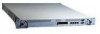
appliances combine the power of the Nokia IPSO operating system and Nokia Secure Access System (Nokia SAS). Both the 60s and 100s platforms share the same one-rack unit (1 RU) size and support the same selection of network interface cards. Memory The Nokia 60s appliance supports from 256 MB to 512 - Nokia IP350 | Installation Guide - Page 18
100s appliances by using the Nokia Network Voyager: Nokia Network Voyager-an SSL-secured, Web-based element management interface. Voyager is preinstalled on the 60s and 100s appliance and enabled through the IPSO operating system. With Voyager, you can manage, monitor, and configure the 60s and 100s - Nokia IP350 | Installation Guide - Page 19
1 Component Locations Front View Status LEDs Modem (AUX) port 60s 00487 PMC interfaces Reset switch PCMCIA slots Console port Built-in Ethernet ports for management connection Figure 2 Component Locations Rear View Power switch 00249 Power plug Nokia 60s and 100s Installation Guide 19 - Nokia IP350 | Installation Guide - Page 20
(green) 00120 RJ-45 connectors Caution Cables that connect to the Ethernet ports must be IEEE 802.3 compliant to prevent potential data loss. The 60s and 100s appliances include two PMC (PCI mezzanine cards) expansion slots for Nokia supported network interface cards. For information about using - Nokia IP350 | Installation Guide - Page 21
. The Nokia Global Support Services group can only provide support for Nokia products that use Nokia-approved accessories. For sales or reseller information, contact a Nokia service provider listed in the "Nokia Contact Information" on page 3. Built-in Console Port Use the built-in console port - Nokia IP350 | Installation Guide - Page 22
1 Overview Built-in AUX Port Use can use the AUX port, shown in Figure 1, to establish a 3 (TXD) 4 (DTR) 5 (GND) 6 (DSR) 7 (RTS) 8 (CTS) 9 (RI) 6 Input/Output 9 700001 To DB25 Cable Out Input 8 (DCD) Input Output Output 2 (TXD) 3 (RXD) 20 (DTR) Input Output Input Output 7 (GND) 6 (DSR) 4 - Nokia IP350 | Installation Guide - Page 23
(NICs) by checking their status LEDs. The system status LEDs are located on the front panel Status LEDs Power-status Voltage Fan problem Table 3 Appliance Status LEDs Status Indication experiencing an internal Voltage problem ! The unit is experiencing a temperature problem ! One or more - Nokia IP350 | Installation Guide - Page 24
by the manufacturer. Dispose of used batteries according to the manufacturer's instructions. Warning To reduce the risk of fire, electric shock, and injury when you use telephone equipment, follow basic safety precautions. Do not use the product near water. 24 Nokia 60s and 100s Installation Guide - Nokia IP350 | Installation Guide - Page 25
long, made of HAR cordage and IEC fittings approved by the country of end use. Software Requirements Nokia 60s and 100s appliances support the following operating system when this guide was published - IPSO v3.8.1 or later. For information about changes to the software requirements or additional - Nokia IP350 | Installation Guide - Page 26
1 Overview 26 Nokia 60s and 100s Installation Guide - Nokia IP350 | Installation Guide - Page 27
2 Installing the Appliance This chapter describes how to install the Nokia 60s and 100s appliances. The following topics are covered: „ Rack Mounting the Appliance 100s appliances mount in a standard 19-inch rack with four mounting screws as Figure 7 shows. Nokia 60s and 100s Installation Guide 27 - Nokia IP350 | Installation Guide - Page 28
2 Installing the Appliance Note To avoid damaging your equipment, Nokia recommends that you use all four rack-mounting screws when you install your appliance on the the unit is 2 inches forward of the rack. Figure 8 Adjustable Mounting Brackets 100s 00488 28 Nokia 60s and 100s Installation Guide - Nokia IP350 | Installation Guide - Page 29
power cord securely into the power socket on the back of the appliance. 2. Plug the other end of the cord into a three-wire grounded power strip or wall outlet. 3. Press the power supply switch to the "on" position to activate the 60s and 100s appliance. Nokia 60s and 100s Installation Guide 29 - Nokia IP350 | Installation Guide - Page 30
, contact your Nokia service provider as listed in "Nokia Contact Information" on page 3 for technical support. Connecting Network Interfaces Connect at least one network interface to use as the Voyager system management interface. This interface is configured during the system startup procedure - Nokia IP350 | Installation Guide - Page 31
connection. This chapter describes how to perform the initial configuration manually by using a console connection. It includes the following sections: „ Using a Console Connection to Perform the Initial Configuration „ Accessing Nokia Network Voyager For information about how to use the DHCP - Nokia IP350 | Installation Guide - Page 32
equipment (DTE) interface or terminal-emulation program configured with the following settings for the console: „ 9600 bps „ 8 data bits „ No parity „ 1 stop bit To connect to the console 1. Connect the supplied null-modem cable (console cable) to the console port on the front panel of the 60s and - Nokia IP350 | Installation Guide - Page 33
an incorrect host name and IP address (this could happen if a DHCP server on your network is configured to respond to any request). To reset the incorrect host name and IP address: a. Establish a console connection to the system. b. Enter the following: Nokia 60s and 100s Installation Guide 33 - Nokia IP350 | Installation Guide - Page 34
appliance. You are prompted to enter the admin username and the password you entered when performing the initial configuration. Note If the username popup menu does not appear, you might not have a network connection between the host and your 60s and 100s 34 Nokia 60s and 100s Installation Guide - Nokia IP350 | Installation Guide - Page 35
Accessing Nokia Network Voyager appliance. Confirm the information you entered during the initial configuration and check that all cables are firmly connected. Accessing Voyager Reference Information As you use Voyager, the Voyager Reference Guide and Voyager inline help are available for you to use - Nokia IP350 | Installation Guide - Page 36
Performing the Initial Configuration You can also access the Voyager Reference Guide at the Nokia support site (https://support.nokia.com) or on is the contextsensitive information source for Voyager. To enable inline help for a specific subject, click the Help icon next to the subject. You can also - Nokia IP350 | Installation Guide - Page 37
„ Configuring and Activating Interfaces „ Monitoring Network Interface Cards For detailed information on specific network interface cards, see Chapter 5, "Connecting PMC Network Interface Cards.". Caution You should have a working knowledge of networking equipment before attempting to service a 60s - Nokia IP350 | Installation Guide - Page 38
Configured Interfaces" for additional information. Use these instructions to remove, install, or replace a NIC in 60s and 100s appliances. Some steps are not applicable to all procedures. The instructions point out steps appropriate to each procedure. 38 Nokia 60s and 100s Installation Guide - Nokia IP350 | Installation Guide - Page 39
assembly is opened, you do not need to manually disconnect the power for this procedure. Any servicing of the unit, however, should be completed cord. 1. Use Network Voyager to shut the system down. For information about how to access Voyager, see "Accessing Nokia Network Voyager" on page 34. 2. Use - Nokia IP350 | Installation Guide - Page 40
unoccupied slot, remove the blank bezel that occupies the space in the appliance front panel, retain it for future use, and proceed to step 7. 40 Nokia 60s and 100s Installation Guide - Nokia IP350 | Installation Guide - Page 41
6. Remove the NIC by lifting the back of the NIC away from the chassis assembly and pulling the NIC gently away from the front panel. Nokia 60s and 100s Installation Guide 00257 41 - Nokia IP350 | Installation Guide - Page 42
of the NIC down toward the chassis assembly. Make sure that the NIC edge is completely seated into the connectors on the chassis assembly. 42 Nokia 60s and 100s Installation Guide - Nokia IP350 | Installation Guide - Page 43
Removing, Installing, and Replacing NICs 8. From the top of the chassis assembly, screw the NIC retaining screws into the standoffs on the back of the NIC. 00255b 9. From beneath the chassis assembly, screw in the bezel retaining screws. Nokia 60s and 100s Installation Guide 00254a 43 - Nokia IP350 | Installation Guide - Page 44
detects any new NIC when the system is restarted. Use Voyager to configure and activate the logical and physical interfaces on the NIC. For information about how to access Voyager and the related reference materials, see "To open Voyager" on page 34. 44 Nokia 60s and 100s Installation Guide - Nokia IP350 | Installation Guide - Page 45
Interface, PMC" on page 47. Use Voyager to access detailed port information. For information about accessing Voyager, see "Accessing Nokia Network Voyager" on page 34. You can also use the IPSO tcpdump command to examine the track on a specific port. Nokia 60s and 100s Installation Guide 45 - Nokia IP350 | Installation Guide - Page 46
4 Installing and Replacing Network Interface Cards 46 Nokia 60s and 100s Installation Guide - Nokia IP350 | Installation Guide - Page 47
, the appliance supports Nokia-approved, dual-port UTP5 dual-mode 10-Mbps and 100-Mbps Ethernet NICs. When you purchase an Ethernet NIC with your 60s and 100s appliance, the NIC is installed before the appliance is delivered to you. For information on Nokia 60s and 100s Installation Guide 47 - Nokia IP350 | Installation Guide - Page 48
supports tracing through tcpdump. You can configure and monitor Ethernet interfaces with Voyager. Specifically, you set the port port Ethernet NIC. Figure 11 Dual-Port Ethernet NIC Front Panel Details Link LEDs (green) NOKIA up. Ethernet NIC Connectors and Cables The connectors on the Ethernet NIC - Nokia IP350 | Installation Guide - Page 49
cable output connector is numbered from right to left, with the copper tabs facing up and toward you. Figure 12 Output Connector for the Ethernet Cable 8 1 00113b Pin# Assignment 1 TX 2 TX 3 RX 4 5 6 RX 7 8 Figure 13 shows the pin assignments for the RJ-45 cross-over cable. Nokia - Nokia IP350 | Installation Guide - Page 50
5 Connecting PMC Network Interface Cards Figure 13 Ethernet Crossover-Cable Pin Connections 00017 50 Nokia 60s and 100s Installation Guide - Nokia IP350 | Installation Guide - Page 51
add or replace user serviceable items other than network interface cards in your 60s and 100s appliance. The following topics are covered: „ Installing a PCMCIA Modem „ Replacing a Hard-Disk Drive „ Replacing or Upgrading Memory „ Installing an Encryption Accelerator Card For instructions on adding - Nokia IP350 | Installation Guide - Page 52
cable for the modem and telephone system in the country in which the device is used. To configure IPSO to allow logins through the modem, click Config on the Home page in Voyager and then click on the Network Access and Services link in the Security and Access Configuration section. 52 Nokia - Nokia IP350 | Installation Guide - Page 53
Drive Location Hard-disk drive 100s 00491 Note The disk drive must contain the IPSO partitions and boot loader before installation. For further information, contact the appropriate Nokia customer support site as listed in "Nokia Contact Information" on page 3. Nokia 60s and 100s Installation Guide - Nokia IP350 | Installation Guide - Page 54
6 Installing and Replacing Other Components To replace a hard-disk drive 1. Use Voyager to shut the system down. For information about how to access Voyager, see "Accessing Nokia Network Voyager" on page 34. 2. Loosen the thumbscrews that hold the chassis assembly. 60s 00487 Chassis assembly - Nokia IP350 | Installation Guide - Page 55
From the bottom of the chassis assembly, remove the retaining screws that hold the hard-disk drive unit. 00261 5. Gently remove the hard-disk drive from the motherboard, taking care not to damage the connector. 6. Insert the new hard-disk drive unit. Nokia 60s and 100s Installation Guide 00262 55 - Nokia IP350 | Installation Guide - Page 56
. Take care to align the connectors correctly as the connectors are not keyed. 7. Tighten the retaining screws that holds the hard-disk drive into place. 00261 8. Slide the chassis assembly back into the appliance until it clicks into place. 100s 00490 56 Nokia 60s and 100s Installation Guide - Nokia IP350 | Installation Guide - Page 57
60s, the system displays a warning message and shuts down. „ The 100s appliance comes with 256 MB of memory in one DIMM and can be upgraded to 512 MB by adding a second 256 MB DIMM, or upgraded to 1 GB by replacing the 256 MB DIMM with two (2) 512 MB DIMMs. Nokia 60s and 100s Installation Guide 57 - Nokia IP350 | Installation Guide - Page 58
support site listed "Nokia Contact Information" on page 3. The DIMM sockets are located at the right of the motherboard, as you look at the appliance from the front, as Figure 15 shows. Figure 15 DIMM Socket Locations DIMM sockets 100s 00492 Before You Start To upgrade or replace the memory - Nokia IP350 | Installation Guide - Page 59
or Upgrading Memory Caution To protect the 60s or 100s appliance and the memory modules is opened, you do not need to manually disconnect the power for this procedure. Any servicing of the unit, however, should be Nokia Network Voyager" on page 34. Nokia 60s and 100s Installation Guide 59 - Nokia IP350 | Installation Guide - Page 60
the chassis assembly forward to expose the DIMM sockets Be careful not to pull the chassis assembly entirely out of the appliance. 100s 00489 60 Nokia 60s and 100s Installation Guide - Nokia IP350 | Installation Guide - Page 61
figure shows. 00263 You might need to pull opposite ends of the DIMM alternately to gradually free it from the contact pins. 5. The memory DIMMs are keyed to prevent improper insertion. Press the new DIMM into the socket until it clicks into place. Nokia 60s and 100s Installation Guide 61 - Nokia IP350 | Installation Guide - Page 62
Other Components The top of the DIMM is smooth. The bottom edge has three different length sets of contacts, which mate with the slots on the socket. Be sure the contacts and slots assembly back into the appliance until it clicks into place. 100s 00490 62 Nokia 60s and 100s Installation Guide - Nokia IP350 | Installation Guide - Page 63
7. Resecure the two thumbscrews. Replacing or Upgrading Memory 60s 00487 Chassis assembly thumbscrews The appliance automatically recognizes the new memory configuration. You can verify this from the Voyager or Lynx interface. Nokia 60s and 100s Installation Guide 63 - Nokia IP350 | Installation Guide - Page 64
software package is part of IPSO, so the appliance automatically detects and configures the card. For tasks related to installing the encryption accelerator card, see "Installing the Card" on page 65 Before You Start Before you install the card, you need: 64 Nokia 60s and 100s Installation Guide - Nokia IP350 | Installation Guide - Page 65
Four screws (included in packaging) „ A disposable wrist strap (included in packaging) Warning To help guard against electrostatic discharge damage, follow the instructions on the wrist strap envelope before you handle the accelerator card or open the appliance. Installing the Card 1. Use Voyager or - Nokia IP350 | Installation Guide - Page 66
for the SSL VPN acceleration card. Do not use the PMC connectors located at the front of the motherboard, those connectors are for NICs. 66 Nokia 60s and 100s Installation Guide - Nokia IP350 | Installation Guide - Page 67
. Screw card into standoffs. 100s 00493 5. Position the male PMC connectors on the card over the female PMC connectors on the motherboard. The two sets of connectors should be aligned with each other. The four screw holes and four standoffs should also be aligned with one another. 6. Push down on - Nokia IP350 | Installation Guide - Page 68
back into the appliance and resecure the two thumbscrews. 60s 00487 Chassis assembly thumbscrews Reseating the chassis assembly automatically restores power to the appliance. 12. Configure your software to use hardware acceleration. For more information, see "" on page 69. 68 - Nokia IP350 | Installation Guide - Page 69
Installing an Encryption Accelerator Card Nokia 60s and 100s Installation Guide 69 - Nokia IP350 | Installation Guide - Page 70
6 Installing and Replacing Other Components 70 Nokia 60s and 100s Installation Guide - Nokia IP350 | Installation Guide - Page 71
System „ Using the Boot Manager to Install IPSO „ Protecting the Boot Manager with a Password „ Installing the Boot Manager „ Upgrading the Boot Manager The Nokia 60s and 100s platforms incorporate a boot manager on disk to control the boot-up process. The boot manager allows you to perform a number - Nokia IP350 | Installation Guide - Page 72
7 Using the Boot Manager the hard-disk drive. You can set these values by using boot manager commands. This chapter describes the boot manager commands. Variables A number of variables are stored by the boot manager in nonvolatile memory. You can set and view most variables from the boot manager - Nokia IP350 | Installation Guide - Page 73
console is marked as insecure, you must enter the root password to access the manager. Verbose Mode: Verbose during device probing and thereafter. boot-device: This is the device from which the boot-file loads. Factory default: wd0. Options: wd0 (hard disk). Nokia 60s and 100s Installation Guide - Nokia IP350 | Installation Guide - Page 74
memory. The command has the following syntax: printenv For example: BOOTMGR[93]> printenv Bootmgr Revision: 3.3,base kernel=3.5.1- 06.12.2002080000 autoboot: YES testboot: NO bootwait: 0 boot-file: boot-flags: boot-device: vendor: Nokia model: IP 74 Nokia 60s and 100s Installation Guide - Nokia IP350 | Installation Guide - Page 75
command to view system information such as CPU speed, memory size, and so forth. The command has the following syntax: sysinfo For example: CPU 0: 700 MHz Pentium-III w ATC Memory: 268435456 (256M bytes) Disk Devices: IO port :30:0:11:7 speed 10M full duplex Nokia 60s and 100s Installation Guide 75 - Nokia IP350 | Installation Guide - Page 76
The default directory is /image on the wd0 device. For example: BOOTMGR[2]> ls wd0 /image/current .description bootmgr etc kernel.debug usr VERSION cdrom ipso.tgz mnt web bin dev kernel sbin Setting the Variables setenv Use the setenv command to set a particular variable. The command has - Nokia IP350 | Installation Guide - Page 77
to be yes, the factory default: BOOTMGR[2]> set-defaults autoboot setalias Use the setalias command to set an alias. The command has the following syntax: setalias name device where name is the alias name, and device the device for which name is the alias. Nokia 60s and 100s Installation Guide 77 - Nokia IP350 | Installation Guide - Page 78
: BOOTMGR[2]> unsetalias disk Other commands halt Use the halt command to halt the system. The command has the following syntax: halt help Use the help command to display a list of the available commands. The command has the following syntax: help or ? 78 Nokia 60s and 100s Installation Guide - Nokia IP350 | Installation Guide - Page 79
memory to see if the corresponding default argument is specified there. If so, it uses that value; if not, it defaults to the values in the following table: Argument boot-device boot-file boot-flags Default wd0 (the hard-disk drive) /image/current/kernel -x Nokia 60s and 100s Installation Guide - Nokia IP350 | Installation Guide - Page 80
boot manager prompts you for your password before allowing you to execute the install command. 2. Enter the information the install command requests (your system IP address, the server IP address, and other information). 3. Reboot the 60s or 100s appliance. 80 Nokia 60s and 100s Installation Guide - Nokia IP350 | Installation Guide - Page 81
or 100s appliance hard disk, you can require that the user enter a password to access the boot manager install command. Use the password command to set the password. Note The password you enter gives you access to the install command in boot manager, not access to IPSO. To set a password 1. At the - Nokia IP350 | Installation Guide - Page 82
command from IPSO (the operating system), not from the boot manager. Note To install the new boot manager, you must be in single-user mode. To install the new boot manager 1. Start the appliance in single-user mode. 2. At the IPSO command prompt, enter: /etc/install_bootmgr wd0 /image - Nokia IP350 | Installation Guide - Page 83
the Nokia Contact Information section at the front of this guide. 2. Start the 60s or 100s appliance in single-user mode. 3. At the IPSO command prompt, enter: /etc/upgrade_bootmgr wd0 /etc/nkipflash The command upgrades the boot manager with the new image (nkipflash), writing it into the hard disk - Nokia IP350 | Installation Guide - Page 84
7 Using the Boot Manager 84 Nokia 60s and 100s Installation Guide - Nokia IP350 | Installation Guide - Page 85
problems. For information about how to troubleshoot routing problems, see "Troubleshooting Routing Problems" on page 95. Unable to Log in to the Console Port- your laptop computer or terminal, the problem is with the terminal or cable and not the appliance. Nokia 60s and 100s Installation Guide 85 - Nokia IP350 | Installation Guide - Page 86
in the instructions for resetting the default password, or contact the Nokia customer support site listed in "Nokia Contact Information" on page 3. Login Prompt Appears, But Password Not Accepted Problem Entered wrong password. Solution Obtain a valid password or set the password to a default value - Nokia IP350 | Installation Guide - Page 87
"" The two double quotation marks at the end of the command properly indicate a blank password. After you execute this command, the system reports that the password was not successfully changed. However, the password is changed and is now newpassword. Nokia 60s and 100s Installation Guide 87 - Nokia IP350 | Installation Guide - Page 88
Nokia Network Voyager" on page 34. 2. Under Configuration Database Management (Config > System Configuration > Manage Configuration Sets), choose the option to create a new factory default configuration. 3. Create the new default configuration. Do Not Get a Login Prompt-Error Messages Appear Problem - Nokia IP350 | Installation Guide - Page 89
duplex setting. Do Not See Interfaces that Should be Present Problem Local 60s and 100s appliance ports do not appear. Solution Your NIC might be defective. Contact the appropriate Nokia customer support site as listed in "Nokia Contact Information" on page 3. Nokia 60s and 100s Installation Guide - Nokia IP350 | Installation Guide - Page 90
LED. Solution You might have set the wrong speed. Verify that the speeds match on each end of the Ethernet connection (10 Mbps or 100Mbps). Problem Port not enabled. Solution Verify from the Interface page in Voyager that the interface port is configured as active. Problem High collision rate on the - Nokia IP350 | Installation Guide - Page 91
the Initial Configuration." Problem No route to network. Solution Check the routing table to see if a route exists to the network where the interface is located. If no route exists, see "Troubleshooting Routing Problems" on page 95. Problem Attached device does not have proper default route or - Nokia IP350 | Installation Guide - Page 92
Problems with Multicast Use tcpdump to view packets. To display packets for a specific interface, use the following command: tcpdump -i interface proto igmp. For more information about how to use the tcpdump command, see the Voyager Reference Guide. Under Routing Options in the Routing Configuration - Nokia IP350 | Installation Guide - Page 93
Solution Check cord. Make sure it is properly seated at both ends. Problem Power supply not providing power. Solution Check power source. If there is no power at the source, take appropriate action such as inserting a new fuse or resetting circuit breaker. Nokia 60s and 100s Installation Guide 93 - Nokia IP350 | Installation Guide - Page 94
8 Troubleshooting Appliance Does Not Recognize New Memory Configuration Problem DIMMs are not properly seated in DIMM sockets. Solution Repeat memory installation procedures. Make sure DIMMs are fully seated in sockets. Be sure DIMMs click into place. Appliance locks up after you upgrade IPSO with a - Nokia IP350 | Installation Guide - Page 95
-102644 autoboot: YES bootwait: 5 boot-file: /image/current/kernel boot-flags: boot-device: wd0 Issue the halt command to restart your appliance. BOOTMGR> halt Troubleshooting Routing Problems Several useful tools are available to troubleshoot routing problems. The first tool is available from the - Nokia IP350 | Installation Guide - Page 96
8 Troubleshooting Note Adding a question mark (?) after any command provides additional command options. Typing a question mark (?) at a prompt provides a list of available commands. hostname[admin]# iclid the output appears in /var/tmp/ipsrd.log. 96 Nokia 60s and 100s Installation Guide - Nokia IP350 | Installation Guide - Page 97
and 100s appliance supports OSPF. If the attached appliance does not support OSPF, configure it with a protocol that the appliance supports and exchange routes with OSPF, or set a default or static route. Note You can also use ICLID to display OSPF details. Nokia 60s and 100s Installation Guide 97 - Nokia IP350 | Installation Guide - Page 98
8 Troubleshooting Common Problems with RIP Use tcpdump to view routing information. Use the following command to display routing updates for a specific interface: tcpdump -i interface proto rip For more information about how to use the tcpdump command, see the Voyager Reference Guide. Under routing - Nokia IP350 | Installation Guide - Page 99
Troubleshooting Routing Problems Problem Routing protocol is not functioning properly. Solution to ensure that each routing protocol is functioning properly, see "Common Problems with OSPF" on page 97 and "Common Problems with RIP" on page 98. Nokia 60s and 100s Installation Guide 99 - Nokia IP350 | Installation Guide - Page 100
8 Troubleshooting 100 Nokia 60s and 100s Installation Guide - Nokia IP350 | Installation Guide - Page 101
Specifications Physical Dimensions Dimensions Weight Height: 1.75 in. (4.45 cm) Width: 17 in. (44 cm) 19 in. (48 cm) rack mountable Depth: 16.12 in. (40.94 cm) 17 lbs. (7.7 kg) base system Space Requirements The Nokia to move air through the appliances Nokia 60s and 100s Installation Guide 101 - Nokia IP350 | Installation Guide - Page 102
the ventilation holes on the 60s or 100s appliance. The appliance might overheat and become damaged. NIC Interfaces Ethernet Cable Type IEEE 802.3 10BASE-T, 100BASE-TX unshielded twisted pair, full-duplex or half-duplex Cable Output Connector RJ-45 102 Nokia 60s and 100s Installation Guide - Nokia IP350 | Installation Guide - Page 103
B Compliance Information This appendix contains the following compliance information: „ Declaration of Conformity „ Compliance Statements „ FCC Notice (US) Nokia 60s and 100s Installation Guide 103 - Nokia IP350 | Installation Guide - Page 104
ISO/IEC Guide 22 and EN 45014: Manufacturer's Name: Manufacturer's Address: Nokia Inc. 313 Fairchild Drive Mountain View, CA 94043-2215 USA declares that the product: Product Name: Model Number: Product Options: Serial Number: Date First Applied: Nokia 60s, Nokia 100s Nokia 60s, Nokia 100s All - Nokia IP350 | Installation Guide - Page 105
1999/5/EC this product complies with the requirements of the Low Voltage Directive 73/23/EEC and the EMC Directive 89/336/EEC with Amendment 93/68/EEC. Alan Hutchinson Manager Regulatory Compliance Engineering Mountain View, California August 2002 Nokia 60s and 100s Installation Guide 105 - Nokia IP350 | Installation Guide - Page 106
Statements This hardware complies with the standards listed in this section. Emissions Standards FCC Part 15 Subpart B Class A EN55022 (CISPR 22 Class A) US/Canada European Community (CE) Safety Standards UL60950 Can/CSA-C22.2 No. 950 US Canada 106 Nokia 60s and 100s Installation Guide - Nokia IP350 | Installation Guide - Page 107
the limits for a Class A digital device, pursuant to Part 15 of the FCC Rules. These limits are designed installed and used in accordance with the instruction, may cause harmful interference to radio communications user's authority to operate the equipment. Nokia 60s and 100s Installation Guide 107 - Nokia IP350 | Installation Guide - Page 108
B Compliance Information 108 Nokia 60s and 100s Installation Guide - Nokia IP350 | Installation Guide - Page 109
IPSO using 72, 80 password protection for 81 upgrading 83 variables used by 72, 79 boot manager revision variable 72 boot-device variable 73 boot-file variable 73 boot-flags variable 73 bootwait variable 72 C commands halt 78 help 78 ICLID 95 install 80 ls 76 printenv 74 setalias 77 set-defaults - Nokia IP350 | Installation Guide - Page 110
to 48 connectors 48 H halt command 78 hard disk drive, replacing 53 help command 78 I ICLID command 95 install command 80 installing network interface cards 38 PCMCIA modem 52 interfaces specifications 102 IPSO, booting 79 M management ports 20 memory capacity 57 upgrading 57 modems, PMCIA 20 - Nokia IP350 | Installation Guide - Page 111
command 75 T technical specifications 101 troubleshooting 85 U unsetalias command 78 unsetenv command 77 upgrading memory 57 V variables autoboot 72 boot flag 73 boot manager 72 boot-device 73 boot-file 73 bootwait 72 setting 76 viewing 74 Voyager opening 34 Nokia 60s and 100s Installation Guide
-
 1
1 -
 2
2 -
 3
3 -
 4
4 -
 5
5 -
 6
6 -
 7
7 -
8
-
9
-
10
-
11
-
12
-
13
-
14
-
15
-
16
-
17
-
18
-
19
-
20
-
21
-
22
-
23
-
24
-
25
-
26
-
27
-
28
-
29
-
30
-
31
-
32
-
33
-
34
-
35
-
36
-
37
-
38
-
39
-
40
-
41
-
42
-
43
-
44
-
45
-
46
-
47
-
48
-
49
-
50
-
51
-
52
-
53
-
54
-
55
-
56
-
57
-
58
-
59
-
60
-
61
-
62
-
63
-
64
-
65
-
66
-
67
-
68
-
69
-
70
-
71
-
72
-
73
-
74
-
75
-
76
-
77
-
78
-
79
-
80
-
81
-
82
-
83
-
84
-
85
-
86
-
87
-
88
-
89
-
90
-
91
-
92
-
93
-
94
-
95
-
96
-
97
-
98
-
99
-
100
-
101
-
102
-
103
-
104
-
105
-
106
-
107
-
108
-
109
-
110
-
111
 |
 |
60s and 100s
Installation Guide
Part No. N451545001 Rev A
Published February 2005