Panasonic AGMX70 AGMX70 User Guide
Panasonic AGMX70 - AV SWITCHER Manual
 |
View all Panasonic AGMX70 manuals
Add to My Manuals
Save this manual to your list of manuals |
Panasonic AGMX70 manual content summary:
- Panasonic AGMX70 | AGMX70 User Guide - Page 1
Digital AV Mixer AG- P Before attempting to connect, operate or adjust this product, please read these instructions completely. - Panasonic AGMX70 | AGMX70 User Guide - Page 2
REMOVE COVER (OR BACK). NO USER SERVICEABLE PARTS INSIDE. REFER TO SERVICING TO QUALIFIED SERVICE PERSONNEL. The lightning flash with arrowhead symbol not installed and used in accordance with the instruction manual, may cause harmful interference to radio communications. Operation of this equipment - Panasonic AGMX70 | AGMX70 User Guide - Page 3
of titles. In addition to the wipe, mix and digital effects, this unit comes with built-in chroma key and luminance key functions. Since its downstream keys, fade controls and audio mixers can also be used, the effects required for AB roll editing can be added by just this one unit. Connectors for - Panasonic AGMX70 | AGMX70 User Guide - Page 4
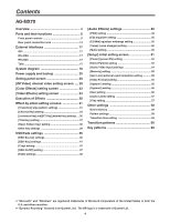
18 Power supply and backup 20 Setting panel screen 20 [INTVideo] internal video setting screen .... 20 [Color Effects] setting screen 23 [Video Effects] setting screen 24 Execution of Effects 30 Effect-by-effect setting screens 31 [Transition] wipe pattern settings 31 [Chroma Key] setting - Panasonic AGMX70 | AGMX70 User Guide - Page 5
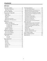
size 75 Image formats supported 75 Management of the image memory 76 Before use 77 AG-MX70 connections 77 Installation of the USB driver 77 For Windows 98 and Windows 2000 77 For Windows ME 78 For Windows XP 78 Installation of MX-Navi 79 Operation confirmation 79 Startup and shutdown - Panasonic AGMX70 | AGMX70 User Guide - Page 6
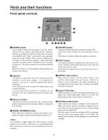
of the blue background when the chroma keys are set. 3 Rotary Z control This control is used to set the key size Z during the key position settings and the luminance setting Y among the color settings. 4 SCENE GRABBER button When this is set to ON with a specific key pattern, it can paste the image - Panasonic AGMX70 | AGMX70 User Guide - Page 7
) button This button is used to reverse the keys and transition key patterns, reverse the frame in/out, and reverse the chroma key, luminance key, external key and title α key signals. The button's lamp flashes with patterns that have no reverse operations, indicating that these patterns cannot - Panasonic AGMX70 | AGMX70 User Guide - Page 8
destination can be previewed; with keys, combined images can be previewed. 2 A/PROG bus selector button This button is used to select the A/PROG bus . Whichever one was selected last takes precedence. In the case of manual strobe, the effect is applied by pressing the button together with "Shift - Panasonic AGMX70 | AGMX70 User Guide - Page 9
used to set the parameter of a selected item. 6 Pattern number display area The transition and key used to set the parameter of a selected item. 8 Setting page display area The name of the page which has been set by the button operations is displayed here. ? Rotary 4 control This control is used - Panasonic AGMX70 | AGMX70 User Guide - Page 10
SET UP INT VIDEO DSK FADE AUDIO EFFECTS @ BCD A LCD CONTRAST control This control is used to adjust the contrast of the LCD display. E> DR D DSK FADE (DSK/fade setting video ME transition or fading. Its function is supported at the ON position. ON or OFF is preset for fading on the DSK/fade - Panasonic AGMX70 | AGMX70 User Guide - Page 11
button is OFF and the pattern number setting button is ON, and the transition times when the pattern number setting button is OFF. 9 "+" key This key is used to increment the event numbers when the event recall button or event setting button is ON, the pattern numbers when the event recall button or - Panasonic AGMX70 | AGMX70 User Guide - Page 12
it is pressed together with the shift key, source 8 is selected. : A/PROG / INT/EXT selector button This button is used to select the image (INT) selected with the shift key, the external input (EXT) is selected. < Transition lever This lever enables transitions to be performed manually. = FADE ( - Panasonic AGMX70 | AGMX70 User Guide - Page 13
Audio mixer area SOURCE 1 / 5 SOURCE 2 / 6 SOURCE 3 / 7 SOURCE 4 / 8 AUX 1 MAX MIC / AUX 2 MASTER MAX MIN MIN 12 3456 7 1 SOURCE 1/5 fader This fader is used to adjust the audio level of input 1 which was set on the initial setting page; when it is operated together with the shift key - Panasonic AGMX70 | AGMX70 User Guide - Page 14
key input connector This connector can be used for key or DSK applications. It can also be used for genlock signal using listed above are used when the optional board (AG-YA70) has uses. 5 G/L (genlock reference) input connectors These are loop-through, automatically terminated connectors. They supply - Panasonic AGMX70 | AGMX70 User Guide - Page 15
Parts and their functions 1 23 4 5 6 7 8 VIDEO IN Y/V PB/V5 PR YC Y/V PB/V6 PR YC Y/V PB/V7 PR 9 :; 1 YC 3 < 2 Y/V PB/V8 PR YC AUDIO IN =>? 4 @ 1 Composite/component Y input 1 connector 2 Composite 5/component PB input 1 connector 3 Component PR input 1 connector 4 YC input 1 - Panasonic AGMX70 | AGMX70 User Guide - Page 16
audio 1 input connectors The audio signals supplied to these connectors are input to the audio signals supplied to these audio signals supplied to these (9-pin) This connector is used to connect the unit with an output. The connector used by the cross point is turned ON. AG-MX70 Example of tally - Panasonic AGMX70 | AGMX70 User Guide - Page 17
RS-232C 25-pin 1 TXD 3 RXD 4 RTS 5 CTS 6 DSR 7 SIG.G 20 DTR AG-MX70 9-pin 1 SPARE 2 RXD 3 TXD 4 DTR 5 SIG.G 6 DSR 9 SPARE [DCE CONNECTION] Use the above conversion with the 9-pin straight cable as well. Editing using the RS-422A, RS-232 and GPI interface connectors ≥ The commands are - Panasonic AGMX70 | AGMX70 User Guide - Page 18
Through connection CPST Y, Pb, Pr Box camera SDI (Video) Box camera SDI (Video) Box camera KEY (Genlock enabled as genlock source) Y, Pb, Pr SDI IN2 SDI IN3 SDI IN4 ADV-REF AG-MX70 SDI OUT Termination VTR SDI MIC (Audio/Video) Microphone Example 2 Live application (2) USB PC (with - Panasonic AGMX70 | AGMX70 User Guide - Page 19
AUX1/AUX2 USB G/L *2 (Genlock enabled as genlock source) Signal generator AG-MX70 SDI OUT RS-422A VTR Analog audio signals CD player, etc. PC using the cross point button. *2: ADV REF can also be used as an alternative to the G/L loop-through signal as the sync signal supplied to the AG- - Panasonic AGMX70 | AGMX70 User Guide - Page 20
Power supply and backup The operation panel settings are stored in the memory when the power is turned off. The default settings are established when the power is turned back on by selecting [Power] > [Reset] on the [Setup] initial setting screen, and the system is started from the settings which - Panasonic AGMX70 | AGMX70 User Guide - Page 21
value from 0 to 255 and [Y] to any value from 16 to 255 but only when [Custom1] or [Custom2] has been selected using rotary 2 control. Colors are selected using the rotary 2 control. There are 10 choices: White, Yellow, Cyan, Green, Magenta, Red, Blue, Black, Custom1 and Custom2. The color level - Panasonic AGMX70 | AGMX70 User Guide - Page 22
the Prog output, and when the image to be written appears, write it using "Enter." In the case of Movie, the images are written consecutively from Memory" again but they will be cleared after the power is turned off. The playback trigger is applied using "Shift" + ".". The "Grade" setting which was - Panasonic AGMX70 | AGMX70 User Guide - Page 23
of the bus to be set while holding down the [Shift] key. Settings can be performed separately for the A bus and B using the joystick's X direction (for adjusting Pb) and rotary 3 control or using the joystick's Y direction (for adjusting Pr) and rotary 4 control, and the chroma gain can be set using - Panasonic AGMX70 | AGMX70 User Guide - Page 24
Width Ripple 0 16 1 R1 R2 R3 R4 R5 Scrolled display This menu is selected using the A or B bus [Video Effects] button. If the status of the [Video Effects] button of the bus to be set while holding down the [Shift] key. Settings can be performed separately for the A bus and B bus. At this - Panasonic AGMX70 | AGMX70 User Guide - Page 25
setting can be changed in 2step increments. The default setting is 8. This level setting is used for the level of transition numbers 1001, 1002 and 1003 (200, 201 and 202). (monochrome) setting Select [On] or [Off] for this effect using the rotary 2 control. R1 R2 R3 R4 R5 The default setting - Panasonic AGMX70 | AGMX70 User Guide - Page 26
to @16 for a once-only still operation. Select R4 to R16 for repeat operations. The number denotes the number of screens. At the Manual setting, the screen can be stopped by pressing the cross point [Strobe] button with the [Shift] key. This time setting is used for the level of transition numbers - Panasonic AGMX70 | AGMX70 User Guide - Page 27
level of transition number 1034 (211). On 0 - 7 Off [Nega] (negative) setting The Y negative setting and chroma key negative setting can R1 R2 R3 R4 R5 be selected separately using the rotary 2 control and rotary Nega Y C 3 control, respectively. In both cases, the default setting is - Panasonic AGMX70 | AGMX70 User Guide - Page 28
Select [OFF], [Ripple], [Multi] or [Spark] for 3D using the rotary 2 control. This setting is only effective when the 3D optional board (AG-VE70) has been installed. It cannot be made to take effect at the same time as 3D transition or key pattern. The default setting is [Off]. ≥ When [Ripple] has - Panasonic AGMX70 | AGMX70 User Guide - Page 29
to 3303, 3311 to 3313, 3321 to 3323, 3401 to 3478 • 3601 to 3623 • 1601 to 2999 • 4601 to 6999 2Dcomp Slide 2Dcomp/Move 2Dcomp Key Bounce keys Transition patterns Key patterns 29 - Panasonic AGMX70 | AGMX70 User Guide - Page 30
Preview connector. In the case of chroma keys, the colors are selected using the cursor on the preview screen. 3) Pattern selection Select the pattern using the direct transition button or using the number keys. Patterns with numbers 3000 and up are key patterns. Perform the border, shadow, trail - Panasonic AGMX70 | AGMX70 User Guide - Page 31
are stored for each pattern group. [Transition] wipe pattern settings The transition wipe patterns (numbers 1 to 2999) are opened directly or when selected using the number keys. When transition numbers 200 to 222 (1001 to 1004, 1021 to 1023, 1030 to 1034 and 1059 to 1069) and 1981 to - Panasonic AGMX70 | AGMX70 User Guide - Page 32
for the direct pattern. Select [Hard], [Soft], [Border] or [Soft Border] using the rotary 2 control. The default setting is [Hard]. When [Soft] or [Soft be selected. The [Width] thickness can be set to any value from 1 to 255 using the rotary 3 control. The default setting is 32. Only 1 or 2 can be - Panasonic AGMX70 | AGMX70 User Guide - Page 33
perform the DVE settings. Select the [Off], [Shadow] or [Trail] effect using the rotary 2 control. Set the [Light] (lighting) using the rotary 5 control. This is valid only when the 3D optional board (AG-VE70) has been installed for use. ≥ When [Shadow] has been set When [Shadow] has been selected - Panasonic AGMX70 | AGMX70 User Guide - Page 34
Effect-by-effect setting screens [Chroma Key] setting The chroma key is opened directly or when selected using the number keys. ME is automatically selected for the Preview output, and the chroma key cursor and keyed output are displayed. Pos. X 128 Y 128 Z 196 Event ME Time 00E 10:00F Pattern - Panasonic AGMX70 | AGMX70 User Guide - Page 35
- 255 0 - 3 0 - 15 [Crop] setting This is used to perform the crop settings for the keys. R1 R2 R3 R4 R5 These settings can be performed separately with [ effect only when the 3D optional board (AG-VE70) has been installed. It is possible to add the DVEs in key numbers 3401 to 3478, 3601 to - Panasonic AGMX70 | AGMX70 User Guide - Page 36
by-effect setting screens [Luminance Key] and [EXT Key] (external key) settings The luminance key and external key are opened directly or when selected using the number keys. Pos. X 128 Y 128 Z 196 Event ME Time 00E 10:00F Pattern 3102 INT Wht Luminance Key Key Slice Crop A A 6 Effects - Panasonic AGMX70 | AGMX70 User Guide - Page 37
The default setting is 255. The crop setting can also be set separately from the other keys. Effects can be added for the effect settings in the same way as for other patterns. The settings are performed as with the DVE's chroma key. The title key cannot be selected during DSK execution. 37 - Panasonic AGMX70 | AGMX70 User Guide - Page 38
-by-effect setting screens [Basic Pattern Key] setting (numbers 3001 to 3046) The basic pattern key is opened directly or when selected using the number keys. Pos. X 128 Y 128 Z 196 Event ME Time 00E 10:00F Pattern 3002 INT Wht Basic Pattern Key Pattern Edge Width Color K Level Hard - Panasonic AGMX70 | AGMX70 User Guide - Page 39
rotary Z control. With patterns whose positions can be changed, the position can be set using the joystick. Pos' X 128 Y 128 Z 196 Event ME Time 00E 10:00F Pattern 3301 INT Wht Pattern Key Pattern Edge Width Color K Level Hard 16 White 255 Crop A A 6 8 7 2 12 12 Effects Off - Panasonic AGMX70 | AGMX70 User Guide - Page 40
6001 to 6438 and 6601 to 6716) when the 3D optional board (AGVE70) has been installed. The parameters of the pattern for the 3D keys can be changed using the rotary 2, 3, 4 and 5 controls. They can be stored in the memory for each pattern. ≥ With the sphere group (numbers 6001, 6301 to 6438 - Panasonic AGMX70 | AGMX70 User Guide - Page 41
ripple group (number 6031) R2: [Level] (amplitude) setting R3: [Time] setting R4: [Width] setting The position of the ripple center can be changed using [Shift] + XY. ≥ With the spark group (number 6032) R2: [Width] setting R3: [Size] setting R4: [Time] setting ≥ With the melt group (numbers 6033 - Panasonic AGMX70 | AGMX70 User Guide - Page 42
for a pattern which has not yet been set. Select [Setup], [Preview], [CLR] or [All CLR] using the rotary 4 control, and enter the selection using [Enter]. The operation of a set key is reproduced by selecting a pattern with the [Saved] display and then selecting [Preview] followed by [Enter]. When - Panasonic AGMX70 | AGMX70 User Guide - Page 43
00 Paste Exit R1 R2 R3 R4 INT Wht K Level 255 R5 In the key learn editing mode, the key frame number is displayed in [K Frame]. Using the rotary 1 control, the editing items are selected and key frames are set. Key frames 00 to 19 can be set, and they are displayed during editing in - Panasonic AGMX70 | AGMX70 User Guide - Page 44
64 R2: [Rotate] (rotation) setting R3: [Axis] (rotary axis) setting R4: [View] (viewer) setting R5: [Depth] setting 3D parameters are the same as with 3DModify. Key learn is not possible for doors. 44 - Panasonic AGMX70 | AGMX70 User Guide - Page 45
Strobe for channel A are turned OFF when the Transition lever or key size adjustment Z has been changed or the compression rate has been as follows. ≥ When the 3D optional board (AG-VE70) is not installed Pattern number selected Processing after cancel operation 1501 to 1533 (28 to 31, 36 to - Panasonic AGMX70 | AGMX70 User Guide - Page 46
can be changed on the [Setup] setting screen. Set the operation using the rotary 5 control. Either [Write] or [Preview] can be selected. Set [Mode] to [Write], and write the KEY, Y, Pb and Pr external input signals into the memory using [Enter]. What is written is the whole frames of the images - Panasonic AGMX70 | AGMX70 User Guide - Page 47
selected for DSK ME Trig Slide In Slide Out Speed [Key] and [Fill]. On/Off Off Off Off 8 Whether the in or out operation is to be initiated during an ME transition is set using the rotary 2 control. Whether the sliding in operation is to be initiated in the horizontal or vertical direction - Panasonic AGMX70 | AGMX70 User Guide - Page 48
the rotary 2 control. The default setting is [Black]. [On] or [Off] is selected for [Audio] fading using the rotary 3 control. The default setting is [On]. [After] or [Pre] is selected for [Phone] fading using the rotary 4 control. At [After], the sound is heard with the fading effect applied to the - Panasonic AGMX70 | AGMX70 User Guide - Page 49
EQ M Level Freq Q Mid 0 1.01KHz 0.5 Voice Change Pitch Level Off Up 5 Mute Off AB R1 R2 R3 R4 R5 [Audio Effects] is opened using Audio Effects or the ON button. Audio effects can be set for each input. Select the input from [1] (crosspoint 1), [2] (crosspoint 2), [3] (crosspoint - Panasonic AGMX70 | AGMX70 User Guide - Page 50
5 control. The default setting is [0]. The [H Level] treble level can be set in 2 dB intervals to any value from -14 dB to 0 to +14 dB using the rotary 4 control. The default setting is [0]. [EQ Mid] equalizer midrange setting The [M Level] midrange level can be set in 2 dB intervals to any value - Panasonic AGMX70 | AGMX70 User Guide - Page 51
4dB Head 20dB File Empty 1 Save R1 R2 R3 R4 R5 Scrolled display Select the item to be set using the rotary 1 control. Items consist of [Power], [Direct Pattern], [Audio Video], [Memory], [Gen Lock], [Video Format], [System1], [System2], [Bus], [Audio Level] and [File]. The setup settings - Panasonic AGMX70 | AGMX70 User Guide - Page 52
operation is enabled. To execute the demonstration mode again, turn the power off and then back on again. The audio faders can be used selected button flashes. The [Mix], [Chrm] (chroma) key and [Lum] (luminance) key cannot be set. 3. Use the number keys to input the pattern to be assigned. (The - Panasonic AGMX70 | AGMX70 User Guide - Page 53
effects, and if the settings are acceptable, enter them using [Enter], and return to the direct pattern settings. Off R1 R2 R3 R4 R5 If the setting operation is exited part of the way through (by in the memory. The settings of six key patterns and seven transitions patterns are stored in the - Panasonic AGMX70 | AGMX70 User Guide - Page 54
will not be stored in the memory. They are entered using [Enter], and operation returns to the [Audio Video Input] settings. Select A S-1, A S-2, A S-3 or A S-4 as the audio input using the rotary 4 control. Select [ANALOG] or [SDI] using the rotary 5 control. Video input combinations that cannot be - Panasonic AGMX70 | AGMX70 User Guide - Page 55
rotary 3 control. The default setting is 128. Adjust the [SC Phase] (subcarrier phase) using the rotary 4 control. The default setting is 512. [H Phase] and [SC Phase] are stored in the memory separately in accordance with [G/L] or [Ext Key] for the input. R1 R2 R3 R4 R5 Gen Ref In H Phase SC - Panasonic AGMX70 | AGMX70 User Guide - Page 56
taken until the LCD is set to the power saving R1 R2 R3 R4 R5 mode can be selected using the rotary 2 control. System2 LCDStby VBClean DR using the rotary 5 control to set whether restrictions are to be applied to the SDI and component output chroma. If [On] has been selected, the chroma - Panasonic AGMX70 | AGMX70 User Guide - Page 57
settings. When [Save] or [AllCLR] is selected, [OK?] appears. Enter the selection again using [Enter] or cancel using [Shift] + [Enter]. It is also possible to clear all the settings by holding down [Shift] + [Enter] when the power is turned on so that the factory settings are restored. R1 R2 R3 - Panasonic AGMX70 | AGMX70 User Guide - Page 58
by pressing [Shift] + [Enter] when the power is turned on, and restoring the factory settings. Pattern settings Press the [Pattern] button, input the pattern number using the number keys, and execute using [Enter]. If the pattern does not exist, operation will jump to the nearest pattern number - Panasonic AGMX70 | AGMX70 User Guide - Page 59
] takes precedence over [ME], [DSK] and [Fade]. Items selected by ME, DSK or Fade can be set by the rotary controls. The number keys can also be used when Pattern is OFF. The items selected appear on the LCD display. There are three options-ME, DSK and Fade-and they can be - Panasonic AGMX70 | AGMX70 User Guide - Page 60
Transition patterns Basic 1 2 3 4 5 6 7 8 9 10 11 Pair 63 64 65 66 67 68 69 70 Blinds 79 80 81 82 83 84 85 86 87 88 89 Multi H3 301 302 303 304 305 306 307 308 Multi V3 321 322 323 324 325 326 327 328 Multi H6 103 Overlap 341 342 343 344 345 - Panasonic AGMX70 | AGMX70 User Guide - Page 61
Transition patterns Basic 12 13 14 15 16 17 18 19 20 21 22 23 Pair 71 72 73 74 75 76 77 78 Blinds 90 91 92 93 94 95 96 97 98 100 101 102 Multi H3 309 310 311 312 313 314 315 316 317 318 319 320 Multi V3 329 330 331 332 333 334 335 336 337 - Panasonic AGMX70 | AGMX70 User Guide - Page 62
41 1510 1530 ≥ The DVE and Shutter patterns cannot be used for DSK effect. The Comp1 and Comp2 patterns can be used for DSK effect only when the 3D optional board (AG-VE70) has been installed. ≥ Pattern MIX (56) is used for DVE BPreset. ≥ With Comp2, the image at the transition destination - Panasonic AGMX70 | AGMX70 User Guide - Page 63
to which the dissolve effect can be applied. With patterns 60 and 1081 and Tumble, the image at the transition destination cannot be checked using ME preview when the lever is at the end point. 63 - Panasonic AGMX70 | AGMX70 User Guide - Page 64
effect. The Slide1, Slide2, 2D Move1 and 2D Move2 patterns can be used for DSK effect only when the 3D optional board (AG-VE70) has been installed. ≥ Transition patterns 1601 to 2617 can be used only when the 3D optional board (AG-VE70) has been installed. ≥ With Slide2, the image at the transition - Panasonic AGMX70 | AGMX70 User Guide - Page 65
Transition patterns Bounce Overlap +Diss 138 1321 1331 139 322 1332 140 1323 1333 2D Move2 /Exp Overlap +Diss 2D Move2 /Exp Curve2 Overlap +Diss 159 1441 1451 175 1481 1491 160 1442 1452 176 1482 1492 161 1443 1453 177 1483 1493 162 1444 1454 178 1484 1494 163 1445 1455 179 1485 1495 164 - Panasonic AGMX70 | AGMX70 User Guide - Page 66
2411 2471 2412 2472 ≥ The Flip Tumble, Twist and Roll and Page1, 2, 3 patterns cannot be used for DSK Effect. ≥ Transition patterns 1601 to 2617 can be used only when the 3D optional board (AG-VE70) has been installed. ≥ With Flip Tumble, the image at the transition destination cannot be - Panasonic AGMX70 | AGMX70 User Guide - Page 67
+DISS: This denotes a pattern to which the dissolve effect can be applied. With Flip Tumble, the image at the transition destination cannot be checked using ME preview when the lever is at the end point. 67 - Panasonic AGMX70 | AGMX70 User Guide - Page 68
4650 4690 ≥ The key patterns that can be used for DSK Effect are 6001, 6002, 6003, 6006, 6007 and 6101 to 6634. ≥ BasicPattern Key, Basic Key and Title are the key patterns for which Rev can be used. ≥ Key patterns 4601 to 6716 can be used only when the 3D optional board (AG-VE70) has been - Panasonic AGMX70 | AGMX70 User Guide - Page 69
Key patterns Spot Light Back Diss Exp Exp+Diss 3305 2D Move Exp +Diss 3421 3431 2D Move2 ExpCurve2 3461 +Diss 3471 DualPinP Move +Diss 3521 - Panasonic AGMX70 | AGMX70 User Guide - Page 70
Key patterns Pers1 2DComp 4701 +Diss 4741 PersMove1 2DComp 4761 +Diss 4781 PersMove2 2DComp 4801 +Diss 4821 6113 6104 6114 6105 6115 6106 6116 6107 6117 6108 6118 6109 6119 ≥ The key patterns that can be used for DSK Effect are 6001, 6002, 6003, 6006, 6007 and 6101 to 6634 - Panasonic AGMX70 | AGMX70 User Guide - Page 71
Key patterns Pers1 2DComp 4734 +Diss 4754 PersMove1 2DComp 4769 +Diss 4789 4735 4755 4770 4790 4736 4756 4771 4791 4737 4757 4772 4792 4738 4758 - Panasonic AGMX70 | AGMX70 User Guide - Page 72
Key patterns 6714 6705 6715 6706 6716 Key Learn Key Learn1 Key Learn2 Key Learn3 Key Learn4 Key Learn5 Key Learn6 Key Learn7 Key Learn8 Key Key Learn9 Learn10 9000 9001 9791 ≥ The key patterns that can be used for DSK Effect are 6001, 6002, 6003, 6006, 6007 and 6101 to 6634 - Panasonic AGMX70 | AGMX70 User Guide - Page 73
6328 6338 6428 6438 6229 6239 6329 6339 Pers In Move +Diss 6621 6631 6622 6632 6623 6633 6624 6634 Title Key Key Key Key Key Key Key Key Key Key Learn11 Learn12 Learn13 Learn14 Learn15 Learn16 Learn17 Learn18 Learn19 Learn20 Diss 9010 9011 9012 9013 9014 9015 9016 9017 9018 9019 - Panasonic AGMX70 | AGMX70 User Guide - Page 74
below. The PC to be used should meet the following requirements. ∫ USB driver This driver software is for communications when the AGMX70 is connected to a PC via the USB port. ∫ MX-Navi This software is for use when transmitting images from a PC to the AG-MX70 and playing them back and when - Panasonic AGMX70 | AGMX70 User Guide - Page 75
for the Monitor 1 screen differs, depending on the video format setting of the AGMX70 and the MX-Navi settings. NTSC: Monitor 1 screen = 640 a 480 and played back. ∫ Image formats supported It is possible to use the following image formats for playback with the AG-MX70. ≥ TARGA (.tga) 24 bit/ - Panasonic AGMX70 | AGMX70 User Guide - Page 76
from the PC are stored in the AG-MX70's image memory. The memory capacity differs, depending on the AG-MX70's video format setting. NTSC: 30 number of images can be played back. Number of vertical pixels Number of memory pages used NTSC 1 to 60 1/8 page 61 to 120 1/4 page 121 to 240 1/2 page - Panasonic AGMX70 | AGMX70 User Guide - Page 77
will differ slightly, but the driver software can still be installed following the same steps. ≥ Be sure to log on as a user with Administrator rights when installing this software in a PC with Windows 2000. 1) Connect the PC to the AG-MX70 correctly. 2) Turn on the power to the PC. Check that - Panasonic AGMX70 | AGMX70 User Guide - Page 78
search for a better driver," then click on the "Next" button. ∫ For Windows XP Be sure to log on as a user with Administrator rights when installing this software. 1) Connect the PC to the AG-MX70 correctly. 2) Turn on the power to the PC. Check that Windows has started up. 3) Place - Panasonic AGMX70 | AGMX70 User Guide - Page 79
of the software. Use the following procedure to confirm that the software has been installed correctly. 1) Confirm that the PC and the AG-MX70 have been connected correctly and that the power of the AGMX70 is switched on. 2) Select "Programs" > "Panasonic AG-MX70" > "MXNavi" from the Windows Start - Panasonic AGMX70 | AGMX70 User Guide - Page 80
and shutdown How to start up MX-Navi Select "Program" > "Panasonic AG-MX70" > "MX-Navi" from the Windows Start menu. How to shut down MX-Navi Shutdown is possible in the following two ways. ≥ Click the button at the right top of the main window. ≥ Select "Exit" from the "File" menu of the main - Panasonic AGMX70 | AGMX70 User Guide - Page 81
image is reduced and displayed. When several files are used with one title, one of them will be used for the display. The aspect ratio of the reduced Properties window (page 86) will open. 6 ON The operation at the time of DSK ON will be displayed. When double-clicked, the Properties window (page - Panasonic AGMX70 | AGMX70 User Guide - Page 82
value of the data is shown. 5F The number of images of the data is shown. 6 ON The operation at the time of DSK ON will be displayed. When double-clicked, the Properties window (page 86) will open. Duration (This appears only when Auto Trigger of DSK OFF is valid.) Data playback - Panasonic AGMX70 | AGMX70 User Guide - Page 83
writes the data of the saved file into the flash memory of the AG-MX70. Select this menu item after turning on the power while holding down the "0" key and "5" key on the operation panel of the AG-MX70 and setting the AG-MX70 to the flash memory backup mode. A dialog box now appears so select the - Panasonic AGMX70 | AGMX70 User Guide - Page 84
the Comment heading part of the data display. Cursor menu Top This moves the cursor to the start of the transmission list. The same operation can be performed with the operation button or with the HOME key. Jump to 10th Previous This moves the cursor up 10 from the present position. The same - Panasonic AGMX70 | AGMX70 User Guide - Page 85
. Clear all titles This clears all data in the transmission list from the image memory of the AG-MX70. For details, refer to "Clearing Title data" (page 88). The same operation can be performed with the operation button or with "Ctrl" + "T." Auto Take This executes Auto Take using the AG-MX70. 85 - Panasonic AGMX70 | AGMX70 User Guide - Page 86
data to be transmitted to the AG-MX70. Up to 99 Title data items can be registered in the transmission list. Images can be registered as Title data in the transmission list using the following procedure. 1) Select "Open image" from the "File" menu of the main window. The "Open file" dialog will open - Panasonic AGMX70 | AGMX70 User Guide - Page 87
of pixels to be moved per field). This is used for setting the operation when the data is displayed on the screen (DSK ON). ≥ AutoTrigger: This sets the start operation. No check: DSK ON will be performed when the playback button on the main window is pressed or when the DSK button on the - Panasonic AGMX70 | AGMX70 User Guide - Page 88
will be cleared only by a clearing operation or when the power supply of the AG-MX70 is switched off. When space is required for transmission of new data, delete any data that is not required. The clearing operation is performed using the following procedure. 1) Move the cursor to the data to be - Panasonic AGMX70 | AGMX70 User Guide - Page 89
operations Checking the Title data image The image of the data selected on the image display screen can be displayed in the original size so it can be checked. The image display screen can be displayed using one of the following methods. ≥ Select "Preview" from the file menu of the main window - Panasonic AGMX70 | AGMX70 User Guide - Page 90
Other operations Checking the memory status of the AG-MX70 The status of the image memory of the AG-MX70 can be checked on the memory status screen. Select "Tools" > "Memory status" from the menu of the main window to open the memory status screen. 1 2 Changing the AG-MX-70 memory settings The - Panasonic AGMX70 | AGMX70 User Guide - Page 91
playback, INT/EXT must be selected by the AGMX70. Clearing IntVideo data The operation for deletion of transmitted IntVideo data from the image memory of the AG-MX70 is described below. 1) Select "Tools" > "Memory status" from the menu of the main window to open the memory status screen. 2) Left - Panasonic AGMX70 | AGMX70 User Guide - Page 92
Other operations Setting the initial properties The initial values for the properties to be used with new data can be set on the "Initial set of Property Data" setting screen. 1) Select "Initial set of Property Data" from the Tools menu of the main window. The "Initial set of Property Data" setting - Panasonic AGMX70 | AGMX70 User Guide - Page 93
be displayed when the application is shut down. 2 Memory management The operation when the AG-MX70 is connected to the PC is set. When "Memory clear when re-connect" is checked, all Title and IntVideo data will be cleared when the AGMX70 is connected. Check "Clear the protected data" when data with - Panasonic AGMX70 | AGMX70 User Guide - Page 94
List of short-cut keys Move the cursor to the top Home Select all the data Move the cursor back by 10 Left arrow Delete the selected data Move the - Panasonic AGMX70 | AGMX70 User Guide - Page 95
Troubleshooting Contact your dealer if the problem persists even when you have checked the following items. AG-MX70-related problems Problem What to check ≥ The power can not be ≥ Is the plug of the power cable inserted properly in the outlet? switched on. ≥ Has the fan stopped operating - Panasonic AGMX70 | AGMX70 User Guide - Page 96
, the button display may become main window abnormal. is abnormal. Even if this problem should occur, operation of this software will not be influenced. It may be possible to eliminate the problem using one of the following methods. ≥ Update the video card driver to the newest version. ≥ Click - Panasonic AGMX70 | AGMX70 User Guide - Page 97
Specifications [GENERAL] Power Source : 120 V AC, 50/60 Hz Power Consumption : 52 W (with no optional accessories installed), 70 W (with all optional accessories installed) indicates safety information. Operating temperature: Operating Dynamic Rounding processing enabled) Key: 13.5 MHz Y: - Panasonic AGMX70 | AGMX70 User Guide - Page 98
Specifications [VIDEO INPUT/OUTPUT] Component input connectors: Composite input connectors: YC ) BNC a 1 (with loop-through configuration), 1.0 Vp-p, 75 h Composite signal (genlock selection enabled from G/L, EXT-Key) BNC a 2 Y: 1.0 Vp-p, 75 h Pb/Pr (525): 0.525/0.757 Vp-p switchable, 75 h Pb/ - Panasonic AGMX70 | AGMX70 User Guide - Page 99
Specifications [OTHER] Editor: Connectable Editor: Tally Out: GPI: USB: D-sub 9-pin, RS-422A/232C switchable RS-422A protocol; GVG/Sony switchable Panasonic: AG-A850, 1/2) Embedded audio (channels 1/2) [ACCESSORIES] Power cable 1 Operating Instructions 1 MX-Navi installation CD 1 Warranty card - Panasonic AGMX70 | AGMX70 User Guide - Page 100
) 334-4880 Emergency after hour parts orders (800) 334-4881 TECHNICAL SUPPORT: Emergency 24 Hour Service (800) 222-0741 Panasonic Canada Inc. 5770 Ambler Drive, Mississauga, Ontario L4W 2T3 (905) 624-5010 Panasonic de Mexico S.A. de C.V. Av angel Urraza Num. 1209 Col. de Valle 03100 Mexico, D.F. (52
-
 1
1 -
 2
2 -
 3
3 -
 4
4 -
 5
5 -
 6
6 -
 7
7 -
8
-
9
-
10
-
11
-
12
-
13
-
14
-
15
-
16
-
17
-
18
-
19
-
20
-
21
-
22
-
23
-
24
-
25
-
26
-
27
-
28
-
29
-
30
-
31
-
32
-
33
-
34
-
35
-
36
-
37
-
38
-
39
-
40
-
41
-
42
-
43
-
44
-
45
-
46
-
47
-
48
-
49
-
50
-
51
-
52
-
53
-
54
-
55
-
56
-
57
-
58
-
59
-
60
-
61
-
62
-
63
-
64
-
65
-
66
-
67
-
68
-
69
-
70
-
71
-
72
-
73
-
74
-
75
-
76
-
77
-
78
-
79
-
80
-
81
-
82
-
83
-
84
-
85
-
86
-
87
-
88
-
89
-
90
-
91
-
92
-
93
-
94
-
95
-
96
-
97
-
98
-
99
-
100
 |
 |
Before attempting to connect, operate or adjust this product, please read these instructions completely.
AG-
P
Digital AV Mixer