Panasonic AGMX70 AGMX70 User Guide - Page 9
Setting panel area
 |
View all Panasonic AGMX70 manuals
Add to My Manuals
Save this manual to your list of manuals |
Page 9 highlights
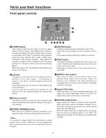
Parts and their functions Setting panel area 25 1 POS. X 119 X 107 Z 235 EVENT METime Pattern INT 4 00E 02:00F 2101 Wht 8 Transition 3 DR 7 6 9 Modify : ; Pattern Edge Hard Effects Off = < Light On CONTRAST ? A SET UP INT VIDEO DSK FADE AUDIO EFFECTS @ B C D E> 1 LCD (liquid crystal) display The effect parameters, time settings and other information are shown on this display. 9 Rotary control setting position display area The currently set positions of the rotary 1, 2, 3, 4 and 5 controls are displayed here. 2 Joystick, Z parameter display area During positioning, the X/Y/Z parameters are displayed here; during the color settings, the Pb/Pr/Y parameters are displayed. 3 Audio level meter This indicates the level of the output sound. 4 Event number display area The event numbers are displayed here. : Scroll bar This displays the position on the page of the item currently displayed. ; Item, parameter setting area The details which are set using the setting pages are switched and displayed here. The selected settings are displayed negatively, and the parameters can each be changed using the rotary 1, 2, 3, 4 and 5 controls. 5 Time display area The ME, DSK and FADE transition times are displayed here. < Rotary 1 control This control is used to set the parameter of a selected item. 6 Pattern number display area The transition and key numbers are displayed here. 7 Internal (internally generated) video display area The settings for the internal video signals are displayed here. = Rotary 2 control This control is used to set the parameter of a selected item. > Rotary 3 control This control is used to set the parameter of a selected item. 8 Setting page display area The name of the page which has been set by the button operations is displayed here. ? Rotary 4 control This control is used to set the parameter of a selected item. @ Rotary 5 control This control is used to set the parameter of a selected item. 9
-
 1
1 -
2
-
3
-
 4
4 -
 5
5 -
 6
6 -
 7
7 -
 8
8 -
 9
9 -
 10
10 -
 11
11 -
 12
12 -
 13
13 -
 14
14 -
15
-
16
-
17
-
18
-
19
-
20
-
21
-
22
-
23
-
24
-
25
-
26
-
27
-
28
-
29
-
30
-
31
-
32
-
33
-
34
-
35
-
36
-
37
-
38
-
39
-
40
-
41
-
42
-
43
-
44
-
45
-
46
-
47
-
48
-
49
-
50
-
51
-
52
-
53
-
54
-
55
-
56
-
57
-
58
-
59
-
60
-
61
-
62
-
63
-
64
-
65
-
66
-
67
-
68
-
69
-
70
-
71
-
72
-
73
-
74
-
75
-
76
-
77
-
78
-
79
-
80
-
81
-
82
-
83
-
84
-
85
-
86
-
87
-
88
-
89
-
90
-
91
-
92
-
93
-
94
-
95
-
96
-
97
-
98
-
99
-
100
 |
 |
