Pioneer DVJ 1000 Owner's Manual - Page 15
Rear panel, Jog dial display - parts
 |
UPC - 012562821481
View all Pioneer DVJ 1000 manuals
Add to My Manuals
Save this manual to your list of manuals |
Page 15 highlights
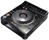
Before Operating (Names and Functions of Parts) Jog dial display 1. Operation display 1 Displays play position, with one revolution equivalent to 135 frames. The display rotates during playback, and stops during pause. 2 2. Cue point position display Displays the position of cue points. 3 3. Audio/video memory status display 4 Flashes during writing to the audio/video memory. While indicator is flashing, it may not be 5 possible to record real time cue points or hot cue points. 4. Jog touch detector indicator When VINYL mode is set to ON, this indicator lights when the top panel of the jog dial is touched. 5. VINYL mode indicator (Vinyl) Lights when VINYL mode is set to ON. Rear panel 5 4 32 1 DIGITAL OUT AUDIO OUT R L CONTROL NORMAL DJ COMPOSITE VIDEO OUT S S PREVIEW OUT SYNC IN POWER OFF ON AC IN 6 7 8 9 1. POWER OFF (-)/ON (_) switch 2. NORMAL/DJ switch ( P.18) If this switch position is changed during playback, playback will stop, and then resume playback from the disc's beginning. DJ: For jog dial, tempo variation and other DJ operations. During DVD playback, subtitles and some other functions, operations, or playback points may not be supported. NORMAL: DJ functions are not supported. Pause mode is silent, not audible. During DVD playback, selected audio signals are output from the digital output connectors. During CD playback, digital data containing subcodes are output (does not support CD graphics). 3. CONTROL connector Using the supplied accessory control cord, this connector can be connected to a Pioneer DJ mixer (sold separately) to allow control of this unit from the DJ mixer. This facilitates the use of functions such as fader start play and back cue. Alternately, linking this connector to another DJ player allows automatic relay play ( P.45). 4. AUDIO OUT L/R connectors RCA type analog audio output connectors. 5. Main video output connectors (VIDEO OUT) Includes RCA and BNC type connectors for outputting DVD playback video only (composite signals), as well as S-Video output connector. 6. DIGITAL OUT connector RCA type coaxial digital output, for connecting AV amplifier, Dolby Digital/DTS decoder, CD recorder, etc. When NORMAL/DJ switch is set to "DJ", during DVD playback the unit outputs 2-channel linear PCM digital data, regardless of the selected audio signal format. During CD playback, the unit outputs only audio data that do not include subcodes. When NORMAL/DJ switch is set to "NORMAL", during DVD playback the unit outputs digital data in the audio signal format selected. During CD playback, the unit outputs digital data including subcodes. 7. Preview video output connectors (PREVIEW OUT) RCA type connector (composite signals) and S-Video output connector. These connectors output monitor images used to aid the DJ during operation. Outputs various guide messages and displays ( P.16). 8. SYNC IN connector BNC type input connector for inputting external sync signal. Use to connect optional dedicated sync signal generator. 9. AC inlet (AC IN) Use auxiliary power cord to connect to standard electrical outlet. 15
-
 1
1 -
2
-
3
-
4
-
5
-
6
-
7
-
8
-
9
-
 10
10 -
 11
11 -
 12
12 -
 13
13 -
 14
14 -
 15
15 -
 16
16 -
 17
17 -
 18
18 -
 19
19 -
 20
20 -
21
-
22
-
23
-
24
-
25
-
26
-
27
-
28
-
29
-
30
-
31
-
32
-
33
-
34
-
35
-
36
-
37
-
38
-
39
-
40
-
41
-
42
-
43
-
44
-
45
-
46
-
47
-
48
-
49
-
50
-
51
-
52
-
53
-
54
-
55
-
56
 |
 |
