RCA DRC8000N User Guide - Page 18
Back of the DVD Recorder
 |
UPC - 034909220382
View all RCA DRC8000N manuals
Add to My Manuals
Save this manual to your list of manuals |
Page 18 highlights
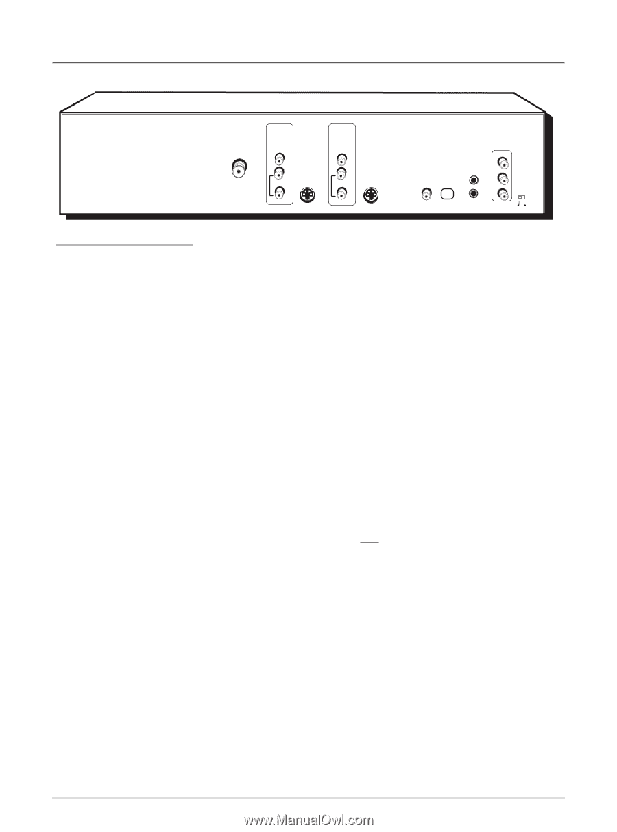
Chapter 1: Connections and Setup INPUT VIDEO OUTPUT VIDEO RF ANTENNA/CABLE INPUT L AUDIO R S-VIDEO IN L AUDIO R S-VIDEO OUT DIGITAL AUDIO OUT COAXIAL OPTICAL COMPONENT VIDEO OUTPUT Y G-LINK IR SAT Pb Pr PROG. SCAN ON OFF Back of the DVD Recorder The back of your recorder might look a little overwhelming at first.This section explains what goes where and why.There are two sets of jacks on the back of your DVD Recorder - INPUT jacks and OUTPUT jacks. Each jack is explained individually below, but the basic idea is about sending and receiving information to be played on or through your DVD Recorder and displaying that information on your TV screen.We call it Signal Flow. INPUT The cables connected to INPUT jacks bring the signal that carries the content INTO the DVD Recorder, such as the cable signal (programming) from the cable company or satellite programming from a satellite receiver. OUTPUT The cables connected to the OUTPUT jacks are sending the signal from the DVD Recorder to the TV so you can see it on the screen.The correct cables must be connected to the DVD Recorder's Output jacks and the corresponding Input Jacks on the TV so you can see the program on the TV. Explanation of Jacks (from left to right) RF ANTENNA/CABLE INPUT: Connect an RF Coaxial cable from an off-air antenna, cable box, or cable outlet to this jack.The cable is sending the programming from the source to the DVD Recorder. Our connections show the cable coming from an 2 Way Splitter (which enables you to watch one program on TV while you record another). INPUT: These jacks receive audio and video from a compatible component, such as a satellite receiver. INPUT 2 jacks are on the front of the DVD Recorder. VIDEO: Color coded yellow, the video cable you use with this jack provides better quality than an RF Coaxial cable but isn't as good as S-Video. Connect corresponding video cable to a compatible component such as a satellite receiver. AUDIO L (left): Color coded white, connect corresponding audio cable to a compatible component such as a satellite receiver. AUDIO R (right): Color coded red, connect corresponding audio cable to a compatible component such as a satellite receiver. S-VIDEO IN: If your satellite receiver has S-VIDEO, connect the S-Video cable to this jack because it provides better picture quality than standard video. OUTPUT: These jacks send the content (audio and video) from your DVD Recorder OUT to the TV so you can see it on the TV screen and hear it through the TV's speakers.There are three video options:VIDEO, S-VIDEO, COMPONENT VIDEO OUTPUT (Y, Pb, Pr). Choose the Video Connection based on your TV's Input Jacks. For more information about jacks and cables, go to page 56. Make sure you connect the AUDIO OUTPUT jacks so you can hear the sound. VIDEO: Color coded yellow, the video cable you use with this jack provides better quality than an RF Coaxial cable but isn't as good as S-Video. AUDIO L (left): Color coded white, connect corresponding audio cable to TV's Audio Left Input Jack. AUDIO R (right): Color coded red, connect corresponding audio cable to TV's Audio Right Input Jack. S-VIDEO OUT: If your TV has S-VIDEO, connect the S-Video cable to this jack because it provides better picture quality than standard composite video. (the yellow jack). DIGITAL AUDIO (OPTICAL and COAXIAL): Use one of these jacks to connect your DVD Recorder to a Dolby Digital or DTS receiver or decoder. Some receivers have either the COAXIAL or OPTICAL type of Digital Audio Input jack, and some have both. Under most conditions, optical and coaxial connections work equally well - the only difference is the type of cable you connect to the jack. Rarely, but sometimes, coaxial digital cables - especially long ones, pick up radio frequency (RF) interference from household appliances, nearby power lines, and/or broadcast towers. If you want to use a less expensive cable, connect a coaxial cable to the COAXIAL jack if your receiver has a Coaxial input jack. 16 Graphics contained within this publication are for representation only.
-
 1
1 -
2
-
3
-
4
-
5
-
6
-
7
-
8
-
9
-
10
-
11
-
12
-
 13
13 -
 14
14 -
 15
15 -
 16
16 -
 17
17 -
 18
18 -
 19
19 -
 20
20 -
 21
21 -
 22
22 -
 23
23 -
24
-
25
-
26
-
27
-
28
-
29
-
30
-
31
-
32
-
33
-
34
-
35
-
36
-
37
-
38
-
39
-
40
-
41
-
42
-
43
-
44
-
45
-
46
-
47
-
48
-
49
-
50
-
51
-
52
-
53
-
54
-
55
-
56
-
57
-
58
-
59
-
60
-
61
-
62
-
63
-
64
 |
 |