RCA DRC8000N User Guide - Page 7
Connection: DVD Recorder + TV - no video
 |
UPC - 034909220382
View all RCA DRC8000N manuals
Add to My Manuals
Save this manual to your list of manuals |
Page 7 highlights
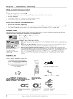
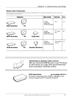
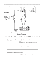
2 Way Splitter (provided) RF Coaxial cable Red White Yellow Audio video cables are usually color-coded red, white, and yellow. Chapter 1: Connections and Setup Connection: DVD Recorder + TV This connection uses the 2-way splitter (provided) so you will be able to watch one program while recording another program. Also, the connection directs you to send the cable/antenna signal to the DVD Recorder so you can utilize the DVD Recorder's onscreen programming guide. 1. Connect the signal (cable or antenna) Note: Depending upon how you currently have your TV connected, you'll have to disconnect the cable from your TV's Antenna Input jack (sometimes labeled CABLE/ANTENNA) before you connect it as explained below. Cable service: If you have cable service via a cable that comes out of the wall, connect the end of that cable to the 2 Way Splitter (provided) - connect the cable to the end of the 2 Way Splitter that only has one connector. Note: If you have a cable box, go to page 6 for connection instructions. Off-air antenna: If you use an off-air antenna to get TV programming, connect the antenna's RF coaxial cable to the end of the 2 Way Splitter that only has one connector. 2. Use the RF Coaxial cable that was packed with your DVD Recorder, and connect one end to the 2 Way Splitter - connect the cable to the end that has two connectors (it doesn't matter which of the two connectors you use). Connect the other end to the RF ANTENNA/CABLE INPUT jack on the back of the DVD Recorder. 3. Connect another RF Coaxial cable (not provided) to the other connector that's available on the 2 Way Splitter. Connect the other end of this RF Coaxial cable to the TV's Antenna Input jack (sometimes labeled CABLE/ANTENNA). Connect the DVD Recorder to the TV 4. You need to connect cables to the DVD Recorder's OUTPUT jacks to the TV's INPUT jacks in order to see the content from the DVD Recorder. 4a. Connect the audio cables. A set of audio/video cables was packed with your DVD Recorder. Connect the audio cables to the OUTPUT AUDIO L (left - white) and R (right - red) jacks on the back of your DVD Recorder, and to the corresponding Audio Input jacks on your TV (sometimes labeled AUDIO IN L and R). 4b. Connect the video cable.The cables you use for the video determine the quality of the picture you'll see on your TV when you're playing DVDs. For more information about cables and signal quality, go to page 56. Connect the video cable (yellow) to the OUTPUT VIDEO jack on the back of your DVD Recorder, and to the Video Input jack on your TV (sometimes labeled VIDEO IN). S-VIDEO (not shown) If your TV has an S-VIDEO jack, connect one end of the S-Video cable (provided) to the S-VIDEO jack on the back of the TV and the other end to the S-VIDEO OUT jack on the back of the DVD Recorder. COMPONENT OUT - Y, Pb, Pr (not shown) If your TV has Component Input Jacks (Y, Pb, Pr), you can achieve even greater picture quality by connecting the DVD Recorder to the TV using these jacks (COMPONENT VIDEO OUTPUT,Y, Pb, Pr on the DVD Recorder). For more explanation, go to page 56. Note: If your TV is capable of progressive scan, connect the DVD Recorder to the TV using the COMPONENT VIDEO OUTPUT jacks, and slide the PROG SCAN switch to the ON position to see DVD titles (movies) in progressive scan format. If you need more explanation, go to page 55. 5. Attach the AC power cord to the unit. 6. Insert the other end of the AC power cord into an AC outlet (or power strip). Go to page 12 Graphics contained within this publication are for representation only. 5
-
 1
1 -
 2
2 -
 3
3 -
 4
4 -
 5
5 -
 6
6 -
 7
7 -
 8
8 -
 9
9 -
 10
10 -
 11
11 -
 12
12 -
13
-
14
-
15
-
16
-
17
-
18
-
19
-
20
-
21
-
22
-
23
-
24
-
25
-
26
-
27
-
28
-
29
-
30
-
31
-
32
-
33
-
34
-
35
-
36
-
37
-
38
-
39
-
40
-
41
-
42
-
43
-
44
-
45
-
46
-
47
-
48
-
49
-
50
-
51
-
52
-
53
-
54
-
55
-
56
-
57
-
58
-
59
-
60
-
61
-
62
-
63
-
64
 |
 |
