Ryobi RY10518 Operator's Manual - Page 32
Maintaining The Safe-t-tip, Guard, Caution, Warning, Maintaining The Guide Bar, Mounting The Safe-t-
 |
View all Ryobi RY10518 manuals
Add to My Manuals
Save this manual to your list of manuals |
Page 32 highlights
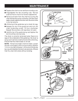
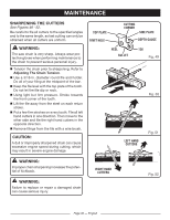
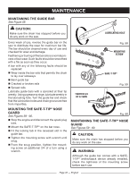
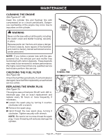
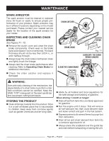
MAINTENANCE MAINTAINING THE GUIDE BAR See Figure 58. CAUTION: Make sure the chain has stopped before you do any work on the saw. LUBRICATING HOLE Every week of use, reverse the guide bar on the saw to distribute the wear for maximum bar life. The bar should be cleaned every day of use and checked for wear and damage. Feathering or burring of the bar rails is a normal process of bar wear. Such faults should be smoothed with a file as soon as they occur. A bar with any of the following faults should be replaced: n Wear inside the bar rails that permits the chain to lay over sideways n Bent guide bar n Cracked or broken rails n Spread rails Lubricate guide bars with a sprocket at their tip weekly. Using a grease syringe, lubricate weekly in the lubricating hole. Turn the guide bar and check that the lubrication holes and chain groove are free from impurities. MOUNTING THE SAFE-T-TIP® NOSE GUARD See Figures 59 - 60. n Stop the engine and disconnect the spark plug wire. n Mount the SAFE-T-TIP® on the bar nose. n Fit the locking tab in the recessed slot in the guide bar. n Tighten the mounting screw with wrench until snug. n From the snug position, tighten the mounting screw an additional 3/4 of a turn using a wrench. Fig. 58 MOUNTING SCREW TIGHTEN 3/4 OF A TURN SAFE-T-TIP® Fig. 59 Fig. 60 MAINTAINING THE SAFE-T-TIP® NOSE GUARD See Figures 59 - 60. CAUTION: Make sure the chain has stopped before you do any work on the saw. WARNING: Although the guide bar comes with a SAFET-TIP® antikickback device already installed, check the tightness of the mounting screw before each use. Page 32 - English
-
 1
1 -
2
-
3
-
4
-
5
-
6
-
7
-
8
-
9
-
10
-
11
-
12
-
13
-
14
-
15
-
16
-
17
-
18
-
19
-
20
-
21
-
22
-
23
-
24
-
25
-
26
-
 27
27 -
 28
28 -
 29
29 -
 30
30 -
 31
31 -
 32
32 -
 33
33 -
 34
34 -
 35
35 -
 36
36 -
 37
37 -
38
-
39
-
40
-
41
-
42
-
43
-
44
-
45
-
46
-
47
-
48
-
49
-
50
-
51
-
52
-
53
-
54
-
55
-
56
-
57
-
58
-
59
-
60
-
61
-
62
-
63
-
64
-
65
-
66
-
67
-
68
-
69
-
70
-
71
-
72
-
73
-
74
-
75
-
76
-
77
-
78
-
79
-
80
-
81
-
82
-
83
-
84
-
85
-
86
-
87
-
88
-
89
-
90
-
91
-
92
-
93
-
94
-
95
-
96
-
97
-
98
-
99
-
100
-
101
-
102
-
103
-
104
-
105
-
106
-
107
-
108
-
109
-
110
-
111
-
112
-
113
-
114
-
115
-
116
-
117
-
118
 |
 |
