Samsung HLN437W User Manual (ENGLISH) - Page 14
Connecting a DTV Set Top Box
 |
UPC - 036725243712
View all Samsung HLN437W manuals
Add to My Manuals
Save this manual to your list of manuals |
Page 14 highlights
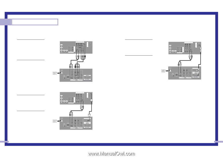
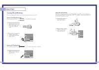
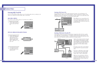
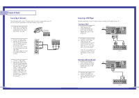
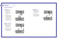
Connections Connecting a DTV Set Top Box Connecting to Y,Pb,Pr 1 Connect a set of audio cables between the Component2 or Component3 AUDIO IN jacks on the TV and the AUDIO OUT jacks on the Set Top Box. 2 Connect video cables between the Component2 or Component3 Y, Pb and Pr inputs on the TV and Y, Pb and Pr (or Y, Cb, Cr) outputs on the Set Top Box. Note: For an explanation of Component video, see your Set Top Box owner's manual. Connecting to DVI (Digital Visual Interface) 1 Connect a set of audio cables between the PC AUDIO IN jacks on the TV and the AUDIO OUT jacks on the Set Top Box. 2 Connect video cables between the DVI IN jack on the TV and the DVI OUT jack on the Set Top Box. 26 TV Rear Panel Component1 Component1/2 (480i/480p) (480p/720p/10801i) PC AUDIO Y ANT-A Pb ANT A-OUT MONITOR OUT Pr VIDEO 2 L L ANT-B S-VIDEO 1 S-VIDEO 2 VIDEO 1 R R V L R DVI PC RS-232C DTV Set Top Box TV Rear Panel Component1 Component1/2 (480i/480p) (480p/720p/10801i) PC AUDIO Y ANT-A Pb ANT A-OUT MONITOR OUT Pr VIDEO 2 L L ANT-B S-VIDEO 1 S-VIDEO 2 VIDEO 1 R R V L R DVI PC RS-232C DVI DTV Set Top Box Connecting to R,G,B 1 Connect a set of audio cables between the PC AUDIO IN jacks on the TV and the AUDIO OUT jacks on the Set Top Box. 2 Connect video cables between the PC IN jack on the TV and the R.G.B OUT jack on the Set Top Box. TV Rear Panel Component1 Component1/2 (480i/480p) (480p/720p/10801i) PC AUDIO Y ANT-A Pb ANT A-OUT MONITOR OUT Pr VIDEO 2 L L ANT-B S-VIDEO 1 S-VIDEO 2 VIDEO 1 R R V L R DVI PC RS-232C DVI DTV Set Top Box 27
-
 1
1 -
2
-
3
-
4
-
5
-
6
-
7
-
8
-
 9
9 -
 10
10 -
 11
11 -
 12
12 -
 13
13 -
 14
14 -
 15
15 -
 16
16 -
 17
17 -
 18
18 -
 19
19 -
20
-
21
-
22
-
23
-
24
-
25
-
26
-
27
-
28
-
29
-
30
-
31
-
32
-
33
-
34
-
35
-
36
-
37
-
38
-
39
-
40
-
41
-
42
-
43
-
44
-
45
-
46
 |
 |