Sanyo WF10 Instruction Manual, PLV-WF10
Sanyo WF10 - PLV WXGA LCD Projector Manual
 |
UPC - 086483050046
View all Sanyo WF10 manuals
Add to My Manuals
Save this manual to your list of manuals |
Sanyo WF10 manual content summary:
- Sanyo WF10 | Instruction Manual, PLV-WF10 - Page 1
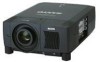
Multimedia Projector MODEL PLV-WF10 ✽ Projection lens is optional. Owner's Manual - Sanyo WF10 | Instruction Manual, PLV-WF10 - Page 2
projector from the power outlet. READ AND KEEP THIS OWNER'S MANUAL FOR LATER USE. CAUTION RISK OF ELECTRIC SHOCK DO NOT OPEN CAUTION : TO REDUCE THE RISK OF ELECTRIC SHOCK, DO NOT REMOVE COVER (OR BACK). NO USERSERVICEABLE PARTS INSIDE EXCEPT LAMP REPLACEMENT. REFER SERVICING TO QUALIFIED SERVICE - Sanyo WF10 | Instruction Manual, PLV-WF10 - Page 3
all warnings and instructions marked on the projector. For added protection to the projector during a lightning storm projector exhibits a distinct change in performance-this indicates a need for service. When replacement parts are required, be sure the service technician has used replacement parts - Sanyo WF10 | Instruction Manual, PLV-WF10 - Page 4
in accordance with the instruction manual, may cause harmful interference REQUIREMENT The AC Power Cord supplied with this projector meets the requirement for use in the country you Fuse covers are available from the Parts Department indicated in your User Instructions. If the plug supplied is not - Sanyo WF10 | Instruction Manual, PLV-WF10 - Page 5
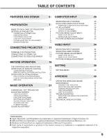
PROJECTOR 21 LAMP MANAGEMENT 45 ADJUSTING SCREEN 22 LAMP REPLACEMENT 46 ZOOM ADJUSTMENT 22 TROUBLESHOOTING 48 FOCUS ADJUSTMENT 22 INDICATORS AND PROJECTOR CONDITION 50 LENS SHIFT ADJUSTMENT 22 MENU TREE 51 KEYSTONE ADJUSTMENT PICTURE FREEZE FUNCTION 22 TECHNICAL SPECIFICATIONS - Sanyo WF10 | Instruction Manual, PLV-WF10 - Page 6
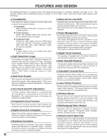
N Keystone Correction Positioning slant of a projector may result in distorted image being displayed in a trapezoid shape. Keystone Correction solves this problem by digitally altering projection to produce undistorted images. N Motor-driven Lens Shift Projection lens can be moved up and down with - Sanyo WF10 | Instruction Manual, PLV-WF10 - Page 7
PREPARATION NAME OF EACH PART OF PROJECTOR FRONT SPEAKERS INFRARED REMOTE RECEIVER PROJECTION LENS LENS COVER CAUTION Do not turn on a projector with lens cover attached. High temperature from light beam may damage lens cover and result in fire hazard. CARRYING HANDLE EXHAUST VENT ADJUSTABLE - Sanyo WF10 | Instruction Manual, PLV-WF10 - Page 8
do not plug into any other type of power system. Consult your authorized dealer or service station if you are not sure of type of power supply being in use. Connect a projector with a peripheral equipment before turning a projector on. (Refer to pages 12 ~ 15 for connection.) Connect AC Power Cord - Sanyo WF10 | Instruction Manual, PLV-WF10 - Page 9
setting up a projector, install Projection Lens on Projector. 1. Before installation, check where a projector is used and prepare suitable lens. For specifications of a Projection Lens, refer to manual separately attached or contact sales dealer where you purchased a projector. 2. For installation - Sanyo WF10 | Instruction Manual, PLV-WF10 - Page 10
lens cap and retract adjustable feet. CAUTION IN CARRYING OR TRANSPORTING A PROJECTOR G Do not drop or bump a projector, otherwise damages or malfunctions may result. G When carrying a projector, use a suitable carrying case. G Do not transport a projector by using a courier or transport service - Sanyo WF10 | Instruction Manual, PLV-WF10 - Page 11
Boards. For Terminal Boards, contact sales dealer where you purchased a projector. INPUT/OUTPUT TERMINALS 3 TERMINAL SLOTS (Factory set) AUDIO CONTROL . Insert terminal along Guide to fit Plug into Socket. 4 Tighten screws to secure terminal. Screws Guide NOTES ON ORDERING OR Optional parts). 11 - Sanyo WF10 | Instruction Manual, PLV-WF10 - Page 12
PORT OUT (MONO) AUDIO OUT R L RESET (MONO) USB INPUT 3 INPUT 2 INPUT 1 INPUT 1, 2 CONTROL PORT CONNECTORS When controlling computer with Remote Control of this projector, connect mouse port of your personal computer to these connectors. (Refer to P14.) INPUT 3 AV INPUT (VIDEO/Y, C) JACKS - Sanyo WF10 | Instruction Manual, PLV-WF10 - Page 13
OUT R L RESET (MONO) USB INPUT 3 INPUT 2 INPUT 1 USB PORT (Series B) This port is used to control a projector with computer. It is also used to control computer with Remote Control of this projector. (Refer to P41, 43.) Connect USB port of computer to this port. R/C JACK When using Wired - Sanyo WF10 | Instruction Manual, PLV-WF10 - Page 14
Port Terminal Terminal Terminal DVI Cable DVI-VGA Cable Terminals of a Projector Switches of MAC/VGA Adapter MAC/VGA ADAPTER ON ON DIP below depending on RESOLUTION MODE that you want to use before your turn on a projector and computer MODE SWITCHES 1 2 3 4 5 6 13"MODE (640 x 480 - Sanyo WF10 | Instruction Manual, PLV-WF10 - Page 15
R L (MONO) R/C JACK RESET SERIAL PORT IN SERIAL PORT OUT AUDIO OUT R L (MONO) USB INPUT 3 INPUT 2 INPUT 1 Audio Cable (Stereo) ✽ AV AUDIO IN Terminals of a Projector AUDIO OUT Audio Cable (Stereo) ✽ Audio Input External Audio Equipment Audio Amplifier Audio Speaker (stereo) 15 - Sanyo WF10 | Instruction Manual, PLV-WF10 - Page 16
VOLUME INPUT AUTO PC ADJ. IMAGE LENS SHIFT MENU SELECT LAMP WARNING REPLACE TEMP. READY LAMP LAMP REPLACE INDICATOR Turns to yellow when life of a projection lamp draws to an end. (P4547) WARNING TEMP. INDICATOR Flashes red when internal projector temperature is too high. (P43) READY - Sanyo WF10 | Instruction Manual, PLV-WF10 - Page 17
as shown in table below depending on Code No. that you want to select remote control code. (Refer to P41.) DIP SWITCH SETTING SW4 ........ LASER ON/OFF LASER P-TIMER INPUT 1 ZOOM INPUT 2 INPUT 3 FOCUS LENS NETWORK POWER ON-OFF BUTTON Used to turn projector on or off. (P21) AUTO PC ADJ. BUTTON - Sanyo WF10 | Instruction Manual, PLV-WF10 - Page 18
MENU KEYSTONE LASER P-TIMER INPUT 1 ZOOM INPUT 2 INPUT 3 FOCUS LENS NETWORK NO SHOW BUTTON Used to turn picture into black image. Operating Range Point Remote Control Unit toward projector (Receiver Window) whenever pressing any button. Maximum operating range for Remote Control Unit is - Sanyo WF10 | Instruction Manual, PLV-WF10 - Page 19
You can control and adjust this projector through ON-SCREEN MENU. Refer pressing POINT button(s) on Top Control or on Remote Control Unit. REMOTE CONTROL UNIT AUTO PC ON-OFF D.ZOOM FREEZE UTO C ADJ. IMAGE ZOOM LENS SHIFT MENU COMPUTER 2 SELECT VIDEO FOCUS LENS FLOW OF ON-SCREEN MENU - Sanyo WF10 | Instruction Manual, PLV-WF10 - Page 20
Press MENU BUTTON while connecting to PC input source. GUIDE WINDOW Shows selected item of ONSCREEN MENU. PC SYSTEM /True/Digital zoom +/-] (Refer to P33) SETTING MENU Used to change settings of projector or reset Lamp Replace Counter. (Refer to P39-42) INPUT MENU Used to select input source ( - Sanyo WF10 | Instruction Manual, PLV-WF10 - Page 21
Remote Control Unit, and a message "Power off?" appears on a screen. 2 Press POWER ON-OFF button again to turn off projector. LAMP LAMP, ONCE YOU TURN PROJECTOR projector Filters for dust accumulation. 3. Clean Air Filters. (See "AIR FILTER CARE AND CLEANING" section on page 44.) 4. Turn a projector - Sanyo WF10 | Instruction Manual, PLV-WF10 - Page 22
displayed. 2 Adjust focus of image by pressing FOCUS L/M button(s) . Focus Message disappears after 4 seconds. LENS SHIFT ADJUSTMENT 1 Press LENS SHIFT button on Top Control or on Remote Control Unit. Message "Lens shift" is displayed. 2 Press POINT UP button to move image up, press POINT DOWN - Sanyo WF10 | Instruction Manual, PLV-WF10 - Page 23
, press FREEZE button again or press any other button except POINT / SELECT / RIGHT CLICK / LASER button. NO SHOW FUNCTION Press NO SHOW button on Remote Control Unit to black out a image. To restore to normal, press NO SHOW button again or press any other button except POINT / SELECT / RIGHT - Sanyo WF10 | Instruction Manual, PLV-WF10 - Page 24
. Volume dialog box appears on screen for a few seconds. (+) button to increase volume, and (-) button for decreasing. Mute Press MUTE button on Remote Control Unit to cut off sound. To restore sound to its previous level, press MUTE button again or press Volume (+/-) button(s). Indicates roughly - Sanyo WF10 | Instruction Manual, PLV-WF10 - Page 25
COMPUTER INPUT SELECTING INPUT SOURCE DIRECT OPERATION Select INPUT source by pressing INPUT 1, INPUT 2 and INPUT 3 buttons on Remote Control Unit. Select INPUT source by pressing INPUT L/M button on Top Control. MENU OPERATION 1 Press MENU button and ON-SCREEN MENU will appear. Press POINT - Sanyo WF10 | Instruction Manual, PLV-WF10 - Page 26
to "COMPATIBLE COMPUTER SPECIFICATION" on page 27). When selecting Computer, this projector automatically tunes to manual adjustment is required. (Refer to P29 and 30.) There is no signal input from computer. Make sure connection of computer and a projector is set correctly. (Refer to TROUBLESHOOTING - Sanyo WF10 | Instruction Manual, PLV-WF10 - Page 27
COMPUTER INPUT COMPATIBLE COMPUTER SPECIFICATIONS Basically this projector can accept a signal from all computers with V, H-Frequency mentioned below and less than 230 MHz of Dot Clock. ON-SCREEN DISPLAY VGA 1 VGA 2 VGA 3 VGA 4 - Sanyo WF10 | Instruction Manual, PLV-WF10 - Page 28
1280 x 1024 1280 x 1024 1600 x 1200 NOTE : Specifications are subject to change without notice. H-Freq. (kHz) Remote Control Unit. Store adjustment parameters. Adjustment parameters from Auto PC Adjustment can be memorized in this projector through this function, manual adjustments are required. - Sanyo WF10 | Instruction Manual, PLV-WF10 - Page 29
you to precisely adjust several parameters to match with those special signal formats. This projector has 5 independent memory areas to memorize those parameters manually adjusted. This enables you to recall setting for a specific computer whenever you use it. Note : This PC ADJUST Menu cannot be - Sanyo WF10 | Instruction Manual, PLV-WF10 - Page 30
SELECT button at Display area icon and Display area dialog box appears. Display area Display area V Adjustment of vertical area displayed with this projector. Press POINT LEFT/RIGHT button(s) to decrease/increase value and then press SELECT button. Full screen Press POINT LEFT/RIGHT button(s) to - Sanyo WF10 | Instruction Manual, PLV-WF10 - Page 31
among Standard, Real, Image 1, Image 2, Image 3 and Image 4 by pressing IMAGE button on Top Control or on Remote Control Unit. Standard Normal picture level preset on this projector. Real Picture level with improved halftone for graphics. IMAGE 1~4 User preset picture adjustment in IMAGE ADJUST Menu - Sanyo WF10 | Instruction Manual, PLV-WF10 - Page 32
. Dialog box display is changed to "On" to reduce noise (rough parts) of image. Press POINT LEFT/RIGHT button(s) again, to change noise LEFT/RIGHT button(s) again, progressive scan mode to on. 3 Store To store manually preset image, move a red frame pointer to Store icon and press SELECT button. - Sanyo WF10 | Instruction Manual, PLV-WF10 - Page 33
projected image can be also expanded by pressing D.ZOOM L button on Remote Control Unit. Digital Zoom - When Digital zoom - is selected, ON "480p" or "575p" is selected on PC SYSTEM Menu (P26). G This projector can not display any resolution higher than 1600 X 1200. If your computer's screen - Sanyo WF10 | Instruction Manual, PLV-WF10 - Page 34
VIDEO INPUT SELECTING INPUT SOURCE WHEN SELECT INPUT 2 (5 BNC INPUT JACKS ) When connect component video output (Cr, Y, Cb or Pr, Y, Pb) from INPUT MENU video equipment to R/Pr, G/Y and B/Pb jacks. 1 Press MENU button and ON-SCREEN MENU will appear. Press POINT LEFT/RIGHT button to move a red - Sanyo WF10 | Instruction Manual, PLV-WF10 - Page 35
optimize its performance. When Video System is PAL-M or PAL-N, select system manually first. PAL / SECAM / NTSC / NTSC4.43 / PAL-M / PAL-N If projector can not reproduce proper video image, it is necessary to select a specific broadcast signal format among PAL, SECAM, NTSC, NTSC 4.43, PAL-M, and PAL - Sanyo WF10 | Instruction Manual, PLV-WF10 - Page 36
among Standard, Cinema, Image 1, Image 2, Image 3 and Image 4 by pressing IMAGE button on Top Control or on Remote Control Unit. Standard Normal picture level preset on this projector. Cinema Picture level adjusted for picture with fine tone. IMAGE 1~4 User preset picture adjustment in IMAGE ADJUST - Sanyo WF10 | Instruction Manual, PLV-WF10 - Page 37
.) Noise reduction Press POINT LEFT/RIGHT button(s) to change noise reduction mode. Dialog box display is changed to "On" to reduce noise (rough parts) of image. Press POINT LEFT/RIGHT button(s) again, to change noise reduction mode to off. Progressive scan Press POINT LEFT/RIGHT button(s) to change - Sanyo WF10 | Instruction Manual, PLV-WF10 - Page 38
. Image Level Menu Move a red frame pointer to image icon to be set and then press SELECT button. Store icon PICTURE SCREEN ADJUSTMENT This projector has a picture screen resize function, which enables you to display desirable image size. 1 Press MENU button and ON-SCREEN MENU will appear. Press - Sanyo WF10 | Instruction Manual, PLV-WF10 - Page 39
Correct keystone distortion by pressing POINT LEFT/RIGHT button(s). Refer to KEYSTONE ADJUSTMENT on page 22. Blue back When this function is "On," this projector will produce a blue image instead of video noise on screen when any input source is unplugged or turned off. Display This function decides - Sanyo WF10 | Instruction Manual, PLV-WF10 - Page 40
to item and then press POINT LEFT/RIGHT button(s). Lamp Mode This Projector is equipped with 2 Projection Lamps and a number of using lamps can be switched to 2 lamps or 1 lamp. Using 1 lamp maintain life of Projection Lamps. To change over Lamp Mode 1. Press MENU button and ON-SCREEN MENU will - Sanyo WF10 | Instruction Manual, PLV-WF10 - Page 41
and computer. Set mode following steps below. Wireless Mouse mode Select " " when controlling a computer with Remote Control of this projector. Projector mode Select " " when controlling a projector with computer. NOTE: This is provided not for basic operation but for future use. Move - Sanyo WF10 | Instruction Manual, PLV-WF10 - Page 42
then press SELECT button. Another confirmation dialog box appears and select [Yes] and then press SELECT button. Return the projector to Factory default. 12 Message "Lamp replace counter Reset?" is displayed. Move pointer to [Yes] and then press SELECT button. Factory default Quit Closes SETTING - Sanyo WF10 | Instruction Manual, PLV-WF10 - Page 43
, DRAG ON INDICATOR lights green and the remote control is in Drag mode. Use the projector may be blocked. not obstructed. In such an event, reposition a projecFtoOr CsoUSthaLtEVNeSntilation Slots are 2 Air Filter may be clogged with dust particles. Clean Air Filter by following section AIR FILTER - Sanyo WF10 | Instruction Manual, PLV-WF10 - Page 44
out. CAUTION Do not operate a projector with Air Filter removed. Dust may accumulate on LCD Panel and Mirror degrading picture quality. Do not put small parts into Air Intake Vents. It may result in malfunction of a projector. 4 Replace Air Filter and Air Filter Cover properly. Make sure that they - Sanyo WF10 | Instruction Manual, PLV-WF10 - Page 45
Management Function automatically changes combination of lighting lamp (Lamp Mode) by detecting status of lamp. When any of 2 lamps becomes out, Lamp Mode is changed over from 2 lamps to 1 lamp. Lamp Mode can be switched to 2 lamps or 1 lamp manually. Refer to SETTING section on page 39, 40. 12 - Sanyo WF10 | Instruction Manual, PLV-WF10 - Page 46
to cool, for at least 45 minutes before you open Lamp Cover. The inside of a projector can become very hot. CAUTION For continued safety, replace with a lamp assembly of the same type. Do not drop a lamp assembly or touch a glass bulb! The glass can shatter and may cause injury. Follow these - Sanyo WF10 | Instruction Manual, PLV-WF10 - Page 47
give the following information to the dealer. G Model No. of your projector : G Replacement Lamp Type No. : PLV-WF10 POA-LMP73 (Service Parts No. 610 309 3802) LAMP HANDLING PRECAUTIONS This projector uses a high-pressure lamp which must be handled carefully and properly. Improper handling may - Sanyo WF10 | Instruction Manual, PLV-WF10 - Page 48
APPENDIX TROUBLESHOOTING Before calling your dealer or service center for assistance, check matters below once again. 1. Make sure you have connected a projector to your computer or video equipment as described in section "CONNECTING PROJECTOR" on pages 12 ~ 15. 2. Check cable connection. Verify - Sanyo WF10 | Instruction Manual, PLV-WF10 - Page 49
You can often correct operating problems yourself. If a projector fails to work properly, see "TROUBLESHOOTING" section on page 48, 49. To correct failure, try "Solutions". If after following all operating instructions, you find that service is necessary, contact Sanyo Service Station or store where - Sanyo WF10 | Instruction Manual, PLV-WF10 - Page 50
center for service and checkup. Do not leave the projector on. It may cause electric shock or a fire hazard. ✽ The projector is in the Power management mode. • • • on • • • flashing • • • dim • • • off ✽ When the life of the projection lamp draws to an end, the LAMP REPLACE indicator - Sanyo WF10 | Instruction Manual, PLV-WF10 - Page 51
Computer Input/Video Input Input Input 1 Input 2 Input 3 Computer Input System (1) SVGA 1 SVGA 2 SVGA 3 MODE 1 MODE 2 PC Adjust Auto PC Adj. Fine sync. Total dots Horizontal Vertical Current mode Clamp Display area Display area - H Display area - V Full screen Reset Mode free Store Quit - Sanyo WF10 | Instruction Manual, PLV-WF10 - Page 52
Russian Chinese Korean Japanese Quit On/Off On/Off On/Off On/Off On/Off Off Ready Shut down 1-30 Min Quit On/Off 1 Lamp/2 Lamp Code 1 Code 2 Code 3 Code 4 Code 5 Code 6 Code 7 Code 8 Quit Mouse/Projector Off Projector Remote Control Quit Yes / No Yes / No 0 - 63 0 - 63 0 - 63 On/Off On/Off 52 - Sanyo WF10 | Instruction Manual, PLV-WF10 - Page 53
APPENDIX TECHNICAL SPECIFICATIONS Projector Type Dimensions (W x H x D) Net Weight LCD Panel System Panel Resolution Number of Pixels Color System High Definition TV Signal Motorized Lens Shift Scanning Frequency Horizontal Resolution Projection Lamp Input 1 Jacks Input 2 Jacks Input 3 Jacks Other - Sanyo WF10 | Instruction Manual, PLV-WF10 - Page 54
APPENDIX CONFIGURATIONS OF TERMINALS DVI-I TERMINAL (DIGITAL/ANALOG) This terminal accepts only Digital (TMDS) or Analog (RGB) output signal. Connect display output terminal of computer to this terminal with DVI cable (supplied). Pin Configuration C1 C2 C1 Analog Red Input C2 Analog Green Input - Sanyo WF10 | Instruction Manual, PLV-WF10 - Page 55
APPENDIX 55 - Sanyo WF10 | Instruction Manual, PLV-WF10 - Page 56
Printed in Japan Part No. 610 313 0682 (1AA6P1P4462-- M4RA) a SANYO Electric Co., Ltd
-
 1
1 -
 2
2 -
 3
3 -
 4
4 -
 5
5 -
 6
6 -
 7
7 -
8
-
9
-
10
-
11
-
12
-
13
-
14
-
15
-
16
-
17
-
18
-
19
-
20
-
21
-
22
-
23
-
24
-
25
-
26
-
27
-
28
-
29
-
30
-
31
-
32
-
33
-
34
-
35
-
36
-
37
-
38
-
39
-
40
-
41
-
42
-
43
-
44
-
45
-
46
-
47
-
48
-
49
-
50
-
51
-
52
-
53
-
54
-
55
-
56
 |
 |
Owner’s Manual
PLV-WF10
Multimedia Projector
MODEL
✽
Projection lens is optional.