Sharp ER-A450T Dealer Knowledge Book - Page 5
ER-A450T to the ER-02FD floppy disk unit, Please refer to fig. 2 below for the connection pin out
 |
View all Sharp ER-A450T manuals
Add to My Manuals
Save this manual to your list of manuals |
Page 5 highlights
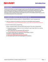
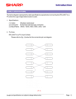
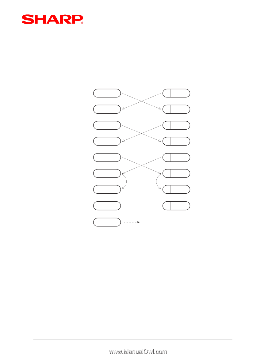
Introduction (2) ER-A450T to the ER-02FD floppy disk unit: Please refer to (fig. 2) below for the connection pin out diagram. 25PIN D-SUB ER-02FD unit SD 2 RD 3 RTS 4 DCD 8 9PIN D-SUB ER-A450T 3 SD 2 RD 7 RTS 1 DCD DTR 20 DSR 6 CTS 5 4 DTR 6 DSR 8 CTS SG 7 5 SG FG 1 FRAME GROUND is connected to the shield of the cable. SD : TRANSMITTED DATA RD : RECEIVED DATA DTR: DATA TERMINAL READY DSR: DATA SET READY RTS: REQUEST TO SEND DCD: DATA CARRIER DETECTOR CTS: CLEAR TO SEND FG : FRAME GROUND (FIG.2) Designs and specifications are subject to change without notice. Page / 4
-
 1
1 -
 2
2 -
 3
3 -
 4
4 -
 5
5 -
 6
6 -
 7
7 -
 8
8 -
 9
9 -
 10
10 -
 11
11 -
12
-
13
-
14
-
15
-
16
-
17
-
18
 |
 |
Introduction
Page
/
4
Designs and specifications are subject to change without notice.
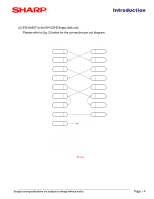
(2)
ER-A450T to the ER-02FD floppy disk unit:
Please refer to (fig. 2) below for the connection pin out diagram.
SD
2
SD
RD
CTS
RD
3
6
5
3
2
6
8
ER-02FD unit
7
5
SG
RTS
4
DCD
8
DTR
20
DSR
7
1
4
ER-A450T
CTS
SG
RTS
DCD
DTR
DSR
1
FG
FRAME GROUND is connected
to the shield of the cable.
25PIN D-SUB
9PIN D-SUB
SD
: TRANSMITTED DATA
RD
: RECEIVED DATA
DTR: DATA TERMINAL READY
DSR: DATA SET READY
RTS: REQUEST TO SEND
DCD: DATA CARRIER DETECTOR
CTS: CLEAR TO SEND
FG
: FRAME GROUND
(F
IG
.2)