Sharp KB-3300JS Service Manual - Page 24
Element Control Systems, Surface
 |
View all Sharp KB-3300JS manuals
Add to My Manuals
Save this manual to your list of manuals |
Page 24 highlights
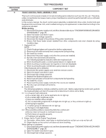
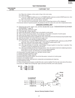
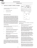
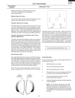
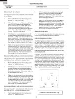
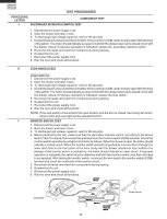
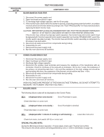
KB-3300JS KB-3300JK KB-3300JW PROCEDURE LETTER TEST PROCEDURES COMPONENT TEST G SURFACE ELEMENT CONTROL SYSTEMS Two types of surface elements control systems are covered in this manual. 1. Standard infinite switch. 2. Dual infinite switch. Contacts Di al Posit ion OFF LO-MED HI L1 - P O L1 - H 1 O L2 - H 2 O X X X X X- C X O - open X - closed Standard infinite switch: The surface elements and standard infinite switches provide an infinite choice of heat settings for cooking. Controls are safety type and must be pushed in before turning. All surface controls are marked on the control panel for their respective heating element. Power is supplied to the surface elements through the infinite switch contacts L1-H1 and L2-H2. During actual surface element operation, if the control is set to the high position contacts L2-H2 are lock closed providing continuous power to the element. In all other setting contacts L2-H2 will cycle to maintain the correct heat setting. Contacts L1P provide power to the surface element indicator light. Element does not heat: Checking the system with a Voltmeter, if the element does not heat up. Troubleshooting: 1. There are four ways a surface control system with a standard infinite switch can fail. 2. 1. The element does not heat. 2. The switch does not cycle the element off and on when set to a position other than high. 3. The element operates correctly, but the indicator light does not glow. 3. 4. Indicator light glows with all infinite switches in the off position. NOTE: If the indicator light glows very dimly with all the switches in the off position. This problem is caused by a capacitive feed over in the wiring and can be corrected by connecting 4. a 100,000 Ohm 1/4 watt resistor in parallel with the light. Continuity tests can be performed on the infinite switch contacts. All tests should be performed with power to the range disconnected, and wiring removed from the switch. Set an ohmmeter on R X 1K scale and check the contacts in the following chart and switch terminal diagram. 5. 22 Remove the back of the control panel to expose the switch terminals. With a Voltmeter set for AC on a scale higher than 240 Volts measure the voltage drop between terminals L1 and L2. If the meter reads zero the wiring between the main terminal block on the range and the switch is open. If the meter reads line to line voltage (around 240 VAC) go to step 3. With the switch turned to the high position measure the voltage drop between terminals H1 and H2. If the meter reads zero the switch is defective. If the meter reads line to line voltage the switch is good. If the range has standard elements go to step 4. If the range has a glass smooth go to step 5. Remove the element and measure the voltage drop between terminals of the terminal block. If the meter reads zero the terminal block or the wiring between the switch and the terminal block is open. If the meter reads line to line voltage the element is defective. NOTE: Always inspect the terminal block for burnt spots that can cause poor connection. Raise the top and locate the two terminals on the element that the wires from H1 and H2 are on. Measure the voltage drop between the two terminals. If the meter reads zero the wires
-
 1
1 -
2
-
3
-
4
-
5
-
6
-
7
-
8
-
9
-
10
-
11
-
12
-
13
-
14
-
15
-
16
-
17
-
18
-
 19
19 -
 20
20 -
 21
21 -
 22
22 -
 23
23 -
 24
24 -
 25
25 -
 26
26 -
 27
27 -
 28
28 -
 29
29 -
30
-
31
-
32
-
33
-
34
-
35
-
36
-
37
-
38
-
39
-
40
-
41
-
42
-
43
-
44
-
45
-
46
-
47
-
48
-
49
-
50
-
51
-
52
-
53
-
54
-
55
-
56
-
57
-
58
-
59
-
60
-
61
-
62
-
63
-
64
-
65
-
66
-
67
-
68
-
69
-
70
-
71
-
72
 |
 |
