Sharp KB-3300JS Service Manual - Page 29
High Voltages Are Present At The High Voltage Terminal, So Do Not Attempt
 |
View all Sharp KB-3300JS manuals
Add to My Manuals
Save this manual to your list of manuals |
Page 29 highlights
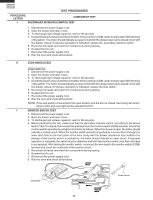
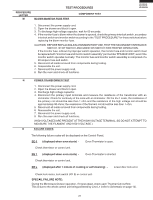
PROCEDURE LETTER M TEST PROCEDURES BLOWN MONITOR FUSE TEST COMPONENT TEST KB-3300JS KB-3300JK KB-3300JW 1. Disconnect the power supply cord. 2. Open the drawer and block it open. 3. To discharge high voltage capacitor, wait for 60 seconds. 4. If the monitor fuse is blown when the drawer is opened, check the primary interlock switch, secondary interlock switch and monitor switch according to the "TEST PROCEDURE" for those switches before replacing the blown monitor fuse. CAUTION: BEFORE REPLACING A BLOWN MONITOR FUSE, TEST THE SECONDARY INTERLOCK SWITCH, STOP SWITCH AND MONITOR SWITCH FOR PROPER OPERATION. If the monitor fuse is blown by improper switch operation, the monitor fuse and monitor switch must be replaced with "monitor fuse and monitor switch assembly" part number FFS-BA018/KIT, even if the monitor switch operates normally. The monitor fuse and monitor switch assembly is comprised of a 20 ampere fuse and switch. 5. Reconnect all leads removed from components during testing. 6. Reassemble the unit. 7. Reconnect the power supply cord. 8. Run the oven and check all functions. N POWER TRANSFORMER TEST 1. Disconnect the power supply cord. 2. Open the drawer and block it open. 3. Discharge high voltage capacitor. 4. Disconnect the primary input terminals and measure the resistance of the transformer with an ohmmeter. Check for continuity of the coils with an ohmmeter. On the R x 1 scale, the resistance of the primary coil should be less than 1 ohm and the resistance of the high voltage coil should be approximately 90 ohms; the resistance of the filament coil should be less than 1 ohm. 5. Reconnect all leads removed from components during testing. 6. Reassemble the unit. 7. Reconnect the power supply cord. 8. Run the oven and check all functions. (HIGH VOLTAGES ARE PRESENT AT THE HIGH VOLTAGE TERMINAL, SO DO NOT ATTEMPT TO MEASURE THE FILAMENT AND HIGH VOLTAGE.) O FAILURE CODES The following failure codes will be displayed on the Control Panel. EE 6 (displayed when oven starts) - Oven Thermistor is open. Check thermistor or control unit. EE 7 (displayed when oven starts) - Oven Thermistor is shorted. Check thermistor or control unit. EE L (displayed after 1 minute of cooking or self cleaning) - Lower door lock error. Check lock motor, lock switch (RY 8) or control unit. SPECAIL FAILURE NOTE: During the Microwave Drawer operation, if it goes dead, check each Thermal Cut-out first. This is due to the whole control unit being powered by Line L1 (refer to Schematic on page 13). 27
-
 1
1 -
2
-
3
-
4
-
5
-
6
-
7
-
8
-
9
-
10
-
11
-
12
-
13
-
14
-
15
-
16
-
17
-
18
-
19
-
20
-
21
-
22
-
23
-
 24
24 -
 25
25 -
 26
26 -
 27
27 -
 28
28 -
 29
29 -
 30
30 -
 31
31 -
 32
32 -
 33
33 -
 34
34 -
35
-
36
-
37
-
38
-
39
-
40
-
41
-
42
-
43
-
44
-
45
-
46
-
47
-
48
-
49
-
50
-
51
-
52
-
53
-
54
-
55
-
56
-
57
-
58
-
59
-
60
-
61
-
62
-
63
-
64
-
65
-
66
-
67
-
68
-
69
-
70
-
71
-
72
 |
 |
