Sharp KB-3300JS Service Manual - Page 26
ment switches off
 |
View all Sharp KB-3300JS manuals
Add to My Manuals
Save this manual to your list of manuals |
Page 26 highlights
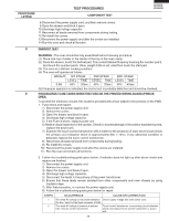
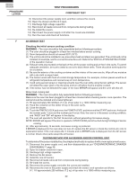
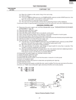
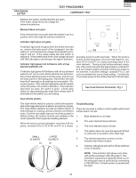
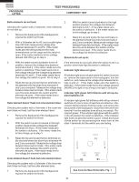
KB-3300JS KB-3300JK KB-3300JW PROCEDURE LETTER TEST PROCEDURES COMPONENT TEST Both elements do not heat: Checking the system with a Voltmeter, if the elements do not heat up: 1. Remove the back panel of the backguard to expose the switch terminals. 2. With a Voltmeter set for AC and a scale higher than 240 Volts measure the voltage drop between terminals P1 and P2. If the meter reads zero the wiring between the main terminal block on the range and the switch is open. If the meter reads line to line voltage (around 240 VAC) go to step 3. 2. With the switch turned clockwise to the high position measure the voltage drop between terminals 4 and 2. If the meter reads zero the switch is defective. If the meter reads line to line voltage, go to step 3. 3. Raise the top and locate the two terminals on the element where the wires from terminals 4 and 2 are connected. Measure the voltage drop between these two terminals. If the meter reads zero the wires between the switch and the element are open. If the meter reads line to line voltage the element is defective. Elements do not cycle: 3. With the switch turned clockwise to the HI position, measure the voltage drop between terminals 4 and 2. If the meter reads zero the switch is defective. If the meter reads line to line voltage measure the voltage drop between terminals 4A and 2. If the meter reads line to line voltage the switch is good. Go to step 4. 4. Raise the top and locate the two terminals on the element with the wires from terminals 4 and 2 are connected. Measure the voltage drop between these two terminals. If the meter reads zero the wires between the switch and the element are open. If the meter reads line to line voltage the element is defective. Outer element doesn't heat, but inner element does: Checking the system with a Voltmeter, if the outer element does not heat, but the inner element does: 1. Remove the back panel of the backguard to expose the switch terminals. 2. With the switch turned clockwise to the high position measure the voltage drop between terminals 4A and 2. If the meter reads zero the switch is defective. If the meter reads line to line voltage, go to step 3. If the elements do not cycle when the switch is set in a position other than high the switch is defective. Indicator light does not glow: If indicator light does not glow when the switch is turned on, remove the back panel of the backguard, turn the switch on, and measure the voltage drop between terminals 4 and L2. If the meter reads zero the switch is defective. If the meter reads line to line voltage (around 240VAC) the light or the wiring to the light is defective. Indicator light glows full brilliance with all top element switches off: If indicator light glows full brilliance with all top element switches off, one or more of switches are defective. Disconnect electrical power from the range, and remove the back panel of the backguard. Disconnect the wire from terminal 4 on the switches from all but one switch. Reconnect power. If the indicator light glows with the switch in the off position the switch is defective. If the indicator light does not glow the switch is good. Check each dual infinite switch by disconnecting the wires from all the other 4 terminals but the switch you are testing. 3. Raise the top and locate the two terminals on the element where the wires from terminals 4A and 2 are connected. Measure the voltage drop between these two terminals. If the meter reads zero the wires between the switch and the element are open. If the meter reads line to line voltage the element is defective. Inner element doesn't heat, but outer element does: Checking the system with a Voltmeter, if the inner element does not heat, but the outer element does: 1. Remove the back panel of the backguard to expose the switch terminals. S2 S1 See Cook Surface Schematic, Fig. 1 24
-
 1
1 -
2
-
3
-
4
-
5
-
6
-
7
-
8
-
9
-
10
-
11
-
12
-
13
-
14
-
15
-
16
-
17
-
18
-
19
-
20
-
 21
21 -
 22
22 -
 23
23 -
 24
24 -
 25
25 -
 26
26 -
 27
27 -
 28
28 -
 29
29 -
 30
30 -
 31
31 -
32
-
33
-
34
-
35
-
36
-
37
-
38
-
39
-
40
-
41
-
42
-
43
-
44
-
45
-
46
-
47
-
48
-
49
-
50
-
51
-
52
-
53
-
54
-
55
-
56
-
57
-
58
-
59
-
60
-
61
-
62
-
63
-
64
-
65
-
66
-
67
-
68
-
69
-
70
-
71
-
72
 |
 |
