Sharp KB-3300JS Service Manual - Page 41
Fig. 6, Fig. 4, Fig. 5
 |
View all Sharp KB-3300JS manuals
Add to My Manuals
Save this manual to your list of manuals |
Page 41 highlights
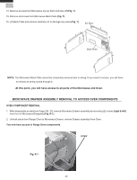
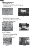
10. Remove screws from Control Panel Frame (Fig 4). Control Panel Frame KB-3300JS KB-3300JK KB-3300JW Fig. 4 11. Slide Cook Top forward to unlock from shoulder screws, then remove or reposition (Fig. 5). Fig. 5 12. Remove all screws on back panel and covers then remove side panels (Fig. 6). 13. Unhook wires from Select Switch assembly by carefully lifting back cover and leaning to gain access (Fig. 6). Fig. 6 Back Panel Select Switch Side Panels 39
-
 1
1 -
2
-
3
-
4
-
5
-
6
-
7
-
8
-
9
-
10
-
11
-
12
-
13
-
14
-
15
-
16
-
17
-
18
-
19
-
20
-
21
-
22
-
23
-
24
-
25
-
26
-
27
-
28
-
29
-
30
-
31
-
32
-
33
-
34
-
35
-
 36
36 -
 37
37 -
 38
38 -
 39
39 -
 40
40 -
 41
41 -
 42
42 -
 43
43 -
 44
44 -
 45
45 -
 46
46 -
47
-
48
-
49
-
50
-
51
-
52
-
53
-
54
-
55
-
56
-
57
-
58
-
59
-
60
-
61
-
62
-
63
-
64
-
65
-
66
-
67
-
68
-
69
-
70
-
71
-
72
 |
 |

39
KB-3300JS
KB-3300JK
KB-3300JW
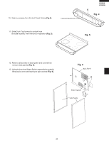
Back Panel
Side Panels
Select Switch
12. Remove all screws on back panel and covers then
remove side panels
(Fig. 6).
13.
Unhook wires from Select Switch assembly by carefully
lifting back cover and leaning to gain access
(Fig. 6).
Fig. 6
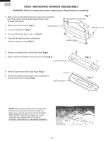
10.
Remove screws from Control Panel Frame
(Fig 4)
.
11. Slide Cook Top forward to unlock from
shoulder screws, then remove or reposition
(Fig. 5)
.
Control Panel Frame
Fig. 4
Fig. 5