Sharp R-209FW Service Manual
Sharp R-209FW Manual
 |
View all Sharp R-209FW manuals
Add to My Manuals
Save this manual to your list of manuals |
Sharp R-209FW manual content summary:
- Sharp R-209FW | Service Manual - Page 1
R-209(IN) R-209(W) R-209(Y) SERVICE MANUAL S3408R209PHW/ MICROWAVE OVEN MODELS R-209(IN) R-209(W) R-209(Y) In interests of user-safety the oven should be restored to its original condition and only parts identical to those specified should be used. TABLE OF CONTENTS Page CAUTION, MICROWAVE - Sharp R-209FW | Service Manual - Page 2
R-209(IN) R-209(W) R-209(Y) CAUTION MICROWAVE RADIATION Personnel should not be exposed to the microwave energy which may radiate from the magnetron or other microwave generating devices if it is improperly used or connected. All input and output microwave connections, waveguides, flanges and - Sharp R-209FW | Service Manual - Page 3
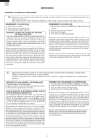
on the parts list may cause undue microwave exposure, by themselves, or when they are damaged, loosened or removed. SERVICING R-209(IN) R-209(W) R-209(Y) PRODUCT SPECIFICATIONS GENERAL INFORMATION APPEARANCE VIEW OPERATING SEQUENCE FUNCTION OF IMPORTANT COMPONENTS TROUBLESHOOTING GUIDE AND TEST - Sharp R-209FW | Service Manual - Page 4
209(IN) R-209(W) R-209(Y) WARNING TO SERVICE PERSONNEL SERVICING GB Microwave ovens contain circuitry capable of producing very high voltage and current, contact with following parts chassis with the use of an insulated screwdriver. Sharp recommend that wherever possible fault-finding is carried - Sharp R-209FW | Service Manual - Page 5
R-209(IN) R-209(W) R-209(Y) änningslikriktaren) till chassiet med hjälp av en isolerad skruvmejsel. Sharp rekommenderar att felsökning sker med strömmen fränkopplad. Ibland anslutningarna till varje enskild komponent på nytt. När all service är klar och ugnen ihopskruvad skall ugnens uteffekt och - Sharp R-209FW | Service Manual - Page 6
R-209(IN) R-209(W) R-209(Y) I I forni a microonde contengono un circuito elettrico in grado di generare tensioni cioè del conduttore di collegamento del raddrizzatore ad alta tensione) sul telaio del forno. Sharp raccomanda, nei limiti del possibile, che la ricerca dei guasti avvenga in assenza di - Sharp R-209FW | Service Manual - Page 7
Cavity Dimensions Turntable diameter Control Complement Set Weight PRODUCT DESCRIPTION R-209(IN) R-209(W) R-209(Y) SPECIFICATION DESCRIPTION 230 Volts 50 Hertz Single phase, 3 wire earthed 1.18 kW 800 W nominal of RF microwave energy (measured by method of IEC 60705) Operating fequency 2450 - Sharp R-209FW | Service Manual - Page 8
12.Outer case 13.Power cord Roller stay Seal packing 1. Place the roller stay on the floor of the oven cavity, engaging shaft into turntable motor shaft. 2. Then place the turntable on the roller stay. CONTROL PANEL MICROWAVE POWER CONTROL knob TIMER knob (0 - 30 minutes) DOOR OPENING BUTTON 6 - Sharp R-209FW | Service Manual - Page 9
) R-209(W) R-209(Y) OFF CONDITION 1. When the timer knob is at " ", the oven is OFF condition. 2. Closing the oven door activates the monitored latch switch and the latch switch. IMPORTANT When the oven door is closed, the contacts (COM-NC) of the monitor switch SW2 must be open. When the microwave - Sharp R-209FW | Service Manual - Page 10
R-209(IN) R-209(W) R-209(Y) FUNCTION OF IMPORTANT COMPONENTS DOOR OPEN MECHANISM The door is fuse F1 T6.3A blows when the contacts (COMNO) of the monitored latch switch SW1 remain closed with the oven door open and when the contacts (COMNC) of the monitor switch SW2 are closes. 2. If the wire - Sharp R-209FW | Service Manual - Page 11
TROUBLESHOOTING GUIDE R-209(IN) R-209(W) R-209(Y) When troubleshooting the microwave oven, it is helpful to follow the Sequence of Operation in performing the checks. Many of the possible causes of trouble H J POSSIBLE CAUSE AND DEFECTIVE PARTS MAGNETRON HIGH VOLTAGE TRANSFORMER H.V. RECTIFIER - Sharp R-209FW | Service Manual - Page 12
209(IN) R-209(W) R-209(Y) PROCEDURE LETTER A MAGNETRON TEST TEST PROCEDURES COMPONENT TEST NEVER TOUCH ANY PART IN THE CIRCUIT WITH YOUR HAND OR AN INSULATED TOOL WHILE THE OVEN load. To measure the microwave output power in the microwave oven, the relation of calorie and watt is used. When P(W) - Sharp R-209FW | Service Manual - Page 13
209(IN) R-209(W) R-209(Y) Room temperature To = 21˚C Initial temperature T1 = 11°C Temperature after (52 + 3) = 55 sec T2 = 21°C Temperature difference Cold-Warm (∆T = T2 - T1 T = 10°C Measured output power The equation is "P = 80 x ∆T P = 80 x 10°C = 800 Watts this part when the oven is on - Sharp R-209FW | Service Manual - Page 14
209(IN) R-209(W) R-209 oven cavity, especially the cooling fan and air guide. CARRY OUT 4R CHECKS. G BLOWN FUSE F1 CARRY OUT 3D CHECKS. 1. If the fuse F1 is blown, there could be a shorts or grounds in electrical parts or wire harness. Check them and replace the defective parts or repair - Sharp R-209FW | Service Manual - Page 15
N and WHITE Between terminal L and RED INDICATION OF OHMMETER Open circuit Short circuit Short circuit R-209(IN) R-209(W) R-209(Y) NOISE the high voltage rectifier or the magnetron. Check them and replace the defective parts and the high voltage fuse. CARRY OUT 4R CHECKS. CAUTION: ONLY REPLACE - Sharp R-209FW | Service Manual - Page 16
ALL ELECTRICAL PARTS ARE USED AT A.C. LINE VOLTAGE. The control unit consists of circuits including semiconductors such as LSI, etc. Therefore, unlike conventional microwave ovens, proper maintenance can not be performed with only a voltmeter and ohmmeter. In this service manual, troubleshooting by - Sharp R-209FW | Service Manual - Page 17
UNIT ASSEMBLY OUTLINE OF CONTROL UNIT R-209(IN) R-209(W) R-209(Y) The control unit consists of the IC-1) 4) Relay Circuit To drive the magnetron, fan motor, turntable motor and light the oven lamp. 5) Synchronizing Signal Circuit The power source synchronizing signal is available in order to - Sharp R-209FW | Service Manual - Page 18
R-209(IN) R-209(W) R-209(Y) DESCRIPTION . L During cooking 10 D2 OUT Signal to check the model. 11 D1 OUT Magnetron high-voltage circuit driving signal. ON relay (RY1). The cro cooking signal holds "L" level during microwave (a. 32second time base) cooking and "H" level while not cooking - Sharp R-209FW | Service Manual - Page 19
and repair the controls of the touch control panel; it is also possible to check the sensor-related controls of the touch control panel by using the dummy resistor(s). 2. Servicing of Touch Control Panel We describe the procedures to permit servicing of the touch control panel of the microwave oven - Sharp R-209FW | Service Manual - Page 20
209(IN) R-209(W) R-209(Y) COMPONENT REPLACEMENT AND ADJUSTMENT PROCEDURE WARNING: Avoid possible exposure to microwave energy. Please follow the instructions below before operating the oven. 1. Disconnect oven from power supply. 2. Make sure that a definite" click" can be heard when the microwave - Sharp R-209FW | Service Manual - Page 21
MAGNETRON REMOVAL R-209(IN) R-209(W) R-209(Y) 1. CARRY OUT 3D CHECKS. 2. Disconnect the wire leads from magnetron. free. Re-install 1. Rest transformer on the bottom plate with its primary terminals toward the oven face plate. 2. Secure transformer with four (4) screws to the bottom plate. 3. Re- - Sharp R-209FW | Service Manual - Page 22
209(IN) R-209(W) R-209(Y) TURNTABLE MOTOR REMOVAL Removal 1. Disconnect the oven from the power supply. 2. Remove the turntable and turntable support from the oven cavity. 3. Turn the oven and metal pieces may be produced. • Do not touch the pliers to the coil of the fan motor because the coil - Sharp R-209FW | Service Manual - Page 23
R-209(IN) R-209(W) R-209(Y) Removal 1. CARRY OUT 3D CHECKS. 2. Remove the single (1) screw holding the green/yellow wire to the oven cavity Install the earth wire lead of power supply cord and the earth angle to the oven cavity with one (1) screw and tight the screw. 3. Connect the brown and - Sharp R-209FW | Service Manual - Page 24
parts. 4. Pry the choke cover by inserting a putty knife in order shown in figure C-5. 5. Release choke cover from door panel. 6. Now choke cover is free. NOTE: When carrying out any repair to the door, do not bend or warp the slit choke (tabs on the door panel assembly) to prevent microwave - Sharp R-209FW | Service Manual - Page 25
Sealer film R-209(IN) R-209(W) R-209(Y) Backing film Adhesive tape Figure C-7. Sealer film MICROWAVE MEASUREMENT After adjustment instruction booklet. Important: Survey instruments that comply with the requirement for instrumentations as prescribed by the performance standard for microwave ovens - Sharp R-209FW | Service Manual - Page 26
R-209(IN) R-209(W) R-209(Y) PARTS Fuse High voltage fuse Temperature fuse (OVEN) Oven lamp High voltage capacitor Magnetron High voltage transformer TEST DATA AT A GLANCE SYMBOL F1 F2 TF OL C MG T VALUE / DATA T6.3A 250V 0.6A 5kV - Sharp R-209FW | Service Manual - Page 27
0.91µF AC2100V T: HIGH VOLTAGE TRANSFORMER WITH THERMAL CUT-OUT 150˚C H.V. RECTIFIER MG: MAGNETRON R-209(IN) R-209(W) R-209(Y) NOTE: " " indicates components with potential above 250V. SW1:MONITORED LATCH SWITCH SCHEMATIC NOTE: CONDITION OF OVEN 1. DOOR CLOSED. NOISE FILTER F1:FUSE T6.3A - Sharp R-209FW | Service Manual - Page 28
WHT 3 BLK CN-A 2 1 GRY ORG ORG RED WHT WHT WHT TF: TEMPERATURE FUSE (OVEN) OL: OVEN LAMP RED WHT GRY GRY 34 ORG RED 12 RED BLK RED TIMER MOTOR GRY N.C. BLK RED VOLTAGE CAPACITOR F2: HIGH VOLTAGE FUSE T: HIGH VOLTAGE TRANSFORMER A A 6 5 4 3 2 1 R-209(IN) R-209(W) R-209(Y) - Sharp R-209FW | Service Manual - Page 29
VOLTAGE TRANSFORMER COM NO D71 1N4005E D72 1N4005E D73 1SS270A + - NOTE : IF NOT SPECIFIED chip parts : 1/10W ± 5% : 0.01µF / 50V R8 15k C3 0.1µ/50v Q1 2SA1267Y R7 1k 15k Q25 KRA101M 4 4 5 5 6 6 R-209(IN) R-209(W) R-209(Y) Figure S-2. Control Unit Circuit A B C D E F G H - Sharp R-209FW | Service Manual - Page 30
R-209(IN) R-209(W) R-209(Y) 1 2 3 4 5 6 A A B R1Y2 OM FA706DR DU VRS1 CNA B 1 3 JP1 D24 (J2) (F1) C2 D2 R5 C5 R11 (ZD1) R10 R6 F F WARNING : AC LINE VOLTAGE IS SUPPLIED TO ALL PARTS WARNING : TRANSLESS G G H 1 Figure S-3. Printed Wiring Board 2 3 4 5 28 H 6 - Sharp R-209FW | Service Manual - Page 31
parts marked "∆" may cause undue microwave exposure. The parts marked "*" are used in voltage more than 250V. R-209(IN) R-209(W) R-209(Y) REF. NO. *C *C F1 * F2 FM FM FM ∆* MG OL OL SW1 SW2 SW3 *T TF TM TTM TTM 1- 1 1- 1 1- 2 * 1- 3 * 1- 3 * 1- 3 2- 1 2- 1 2- 1 2- 2 2- 3 PART Oven lamp 1 Oven - Sharp R-209FW | Service Manual - Page 32
AK AG 6- 1 6- 2 6- 3 6- 4 6- 5 6- 6 MISCELLANEOUS NTNT-A034WRF0 Turntable 1 AM FROLPA101WRKZ Turntable support 1 AR TCAUHA168WRR0 H caution label 1 AH FW-VZB959WREZ Main wire harness 1 AT TINSZA105WRRZ Instruction book in German, French, Dutch, 1 AM Italian, Spanish, Portuguese and - Sharp R-209FW | Service Manual - Page 33
1 2 OVEN PARTS 2-1 A 3 4 5 7-3 7-8 7-3 7-3 R-209(IN) R-209(W) R-209(Y) 6 A B B 7-8 2-3 OL 4-9 7-9 7-3 4-3 C C F1 7-7 7-9 7-3 7-2 7-6 7-1 7-3 1-2 TF MG 4-11 4-4 FM D D 7-1 1-1 6-3 4-9 7-3 7-5 E 4-5 7-3 T E 7-2 4-8 F 6-1 6-2 G 4-1 F 4-12 7-4 SW1 2-2 - Sharp R-209FW | Service Manual - Page 34
R-209(IN) R-209(W) R-209(Y) 1 A B C D E F G H 1 2 3 DOOR PARTS 4 5-6 5 6 A 5-7 5-2 5-8 5-3 3-2 B 5-1 C 5-5 5-4 CONTROL PANEL PARTS D 3-8 3-1 3-5 3-7 E 3-8 3-4 TM F 3-3 3-6 MISCELLANEOUS G 6-4 H Actual wire harness may be different than illustration. 2 3 4 5 6 32 - Sharp R-209FW | Service Manual - Page 35
ACCESSORIES INTO THE OVEN CAVITY DOOR PROTECT SHEET SPADPA580WRE0 6-5 INSTRUCTION BOOK 6-1 TURNTABLE TRAY MICROWAVE OVEN 6-2 TURNRTABLE SUPPORT R-209(IN) R-209(W) R-209(Y) TOP PAD ASSEMBLY FPADBA561WRKZ WRAP COVER SSAKHA014WRE0 BOTTOM PAD ASSEMBLY FPADBA562WRKZ TRAY PAD ASSY (CPADBA287WRKZ) Not - Sharp R-209FW | Service Manual - Page 36
R-209(IN) R-209(W) R-209(Y) '04 SHARP CORP. (3S0EE)
-
 1
1 -
 2
2 -
 3
3 -
 4
4 -
 5
5 -
 6
6 -
 7
7 -
8
-
9
-
10
-
11
-
12
-
13
-
14
-
15
-
16
-
17
-
18
-
19
-
20
-
21
-
22
-
23
-
24
-
25
-
26
-
27
-
28
-
29
-
30
-
31
-
32
-
33
-
34
-
35
-
36
 |
 |
R-209(IN)
R-209(W)
R-209(Y)
TABLE OF CONTENTS
Page
CAUTION, MICROWAVE RADIATION
.................................................................
INSIDE FRONT PAGE
WARNING
.................................................................................................................................................
1
SERVICING
.............................................................................................................................................
2
PRODUCT SPECIFICATIONS
.................................................................................................................
5
GENERAL INFORMATION
.......................................................................................................................
5
APPEARANCE VIEW
..............................................................................................................................
6
OPERATION SEQUENCE
........................................................................................................................
7
FUNCTION OF IMPORTANT COMPONENTS
.......................................................................................
8
TROUBLESHOOTING GUIDE
.................................................................................................................
9
TEST PROCEDURE
..............................................................................................................................
10
CONTROL
PANEL ASSEMBLY
............................................................................................................
15
COMPONENT REPLACEMENT AND ADJUSTMENT PROCEDURE
..................................................
18
MICROWAVE MEASUREMENT
...........................................................................................................
23
TEST DATA AT A GLANCE
..................................................................................................................
24
WIRING DIAGRAM
................................................................................................................................
25
PICTORIAL DIAGRAM
..........................................................................................................................
26
CONTROL PANEL CIRCUIT
..................................................................................................................
27
PRINTED WIRING BOARD
....................................................................................................................
28
PARTS LIST
..........................................................................................................................................
29
S3408R209PHW/
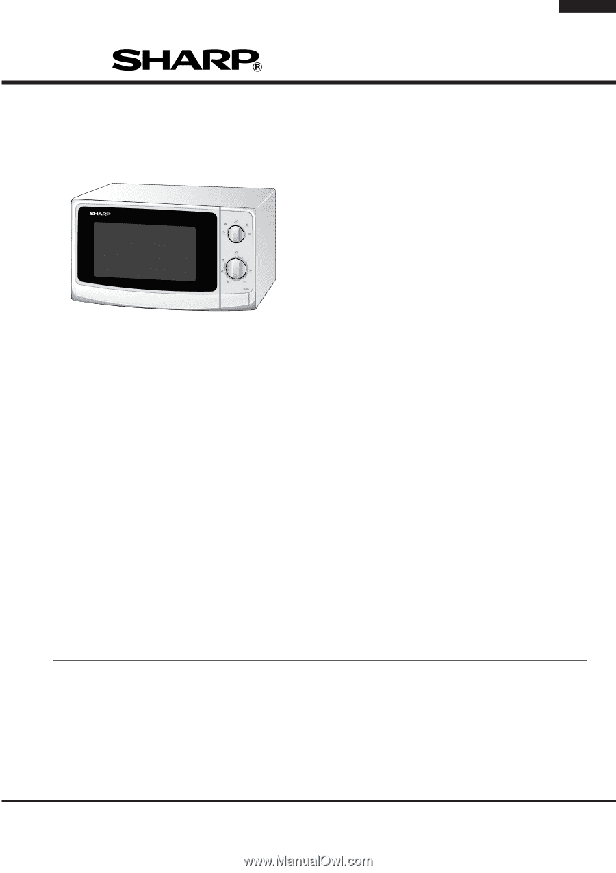
MICROWAVE OVEN
MODELS
R-209(IN)
R-209(W)
R-209(Y)
In interests of user-safety the oven should be restored to its original
condition and only parts identical to those specified should be used.
SERVICE MANUAL
SHARP CORPORATION