Sharp R-209FW Service Manual - Page 22
Turntable Motor Removal, Cooling Fan Motor Removal, Removal, Re-install
 |
View all Sharp R-209FW manuals
Add to My Manuals
Save this manual to your list of manuals |
Page 22 highlights
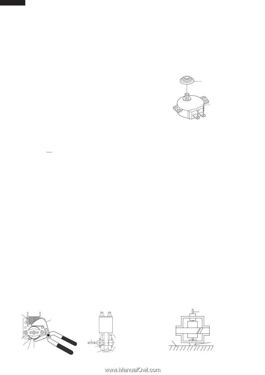
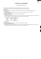
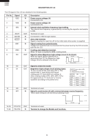
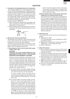
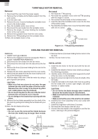
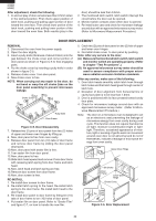
R-209(IN) R-209(W) R-209(Y) TURNTABLE MOTOR REMOVAL Removal 1. Disconnect the oven from the power supply. 2. Remove the turntable and turntable support from the oven cavity. 3. Turn the oven over. 4. Remove the one (1) screw holding the turntable motor cover to the bottom plate. 5. Now, the turntable motor cover is free. 6. Disconnect the wire leads from the turntable motor. 7. Remove the single (1) screw holding the turntable motor to the oven cavity. 8. Remove the turntable motor from the oven cavity. 9. Remove the TTM packing from the turntable motor. 10.Now, the turntable motor is free. Re-install 1. Re-install the TTM packing. 2. Re-install the turntable motor with theTTM packing with the single (1) screw. 3. Re-connect the wire leads to the turntable motor. 4. Insert the tab of the turntable motor cover into the hole of the bottom plate. 5. Re-install the turntable motor cover to the bottom plate with one (1) screw. TTM packing Turntable motor Figure C-2. TTM packing Installation COOLING FAN MOTOR REMOVAL REMOVAL 1. CARRY OUT 3D CHECKS. 2. Remove the magnetron from the waveguide. Refer to chapter "MAGNETRON REMOVAL" 3. Disconnect the wire leads from the fan motor. 4. Disconnect the wire lead from the disconnect the fan duct. 5. Remove the three (3) screws holding the fan duct to the oven cavity. 6. Release the fan motor assembly from the oven cavity. 7. Remove the fan blade from the fan motor shaft accord- ing to the following procedure. 8. Hold the edge of the rotor of the fan motor by using a pair of groove joint pliers. CAUTION: • Make sure that any pieces do not enter the gap between the rotor and the stator of the fan motor. Because the rotor is easy to be shaven by pliers and metal pieces may be produced. • Do not touch the pliers to the coil of the fan motor because the coil may be cut or injured. • Do not disfigure the bracket by touching with the pliers. 9. Remove the fan blade assembly from the shaft of the fan motor by pulling and rotating the fan blade with your hand. 10.Now, the fan blade will be free. CAUTION: • Do not re-use the removed fan blade because the hole (for shaft) may be larger than normal. Coil Groove joint pliers 11.Remove the two (2) screws holding the fan motor to the fan duct. 12.Now, the fan motor is free. INSTALLATION 1. Install the fan motor to the fan duct with the two (2) screws. 2. Install the fan blade to the fan motor shaft according to the following procedure. 3. Hold the center of the bracket which supports the shaft of the fan motor on the flat table. 4. Apply the screw lock tight into the hole (for shaft) of the fan blade. 5. Install the fan blade to the shaft of fan motor by pushing the fan blade with a small, light weight, ball peen hammer or rubber mallet. CAUTION: • Do not hit the fan blade strongly when installed because the bracket may be transformed. • Make sure that the fan blade rotates smooth after installed. • Make sure that the axis of the shaft is not slanted. 6. Install the fan motor assembly to the oven cavity with three (3) screws. 7. Install the magnetron with three (3) screws. 8. Re-install the wire leads of the fan duct. 9. Connect the wire leads to the magnetron and the fan motor, referring to the pictorial diagram. Shaft Stator Gap Bracket Rotor Rear view Shaft Axis Stator Rotor Side view These are the positions that should be pinched with pliers. 20 Table Center of bracket
-
 1
1 -
2
-
3
-
4
-
5
-
6
-
7
-
8
-
9
-
10
-
11
-
12
-
13
-
14
-
15
-
16
-
 17
17 -
 18
18 -
 19
19 -
 20
20 -
 21
21 -
 22
22 -
 23
23 -
 24
24 -
 25
25 -
 26
26 -
 27
27 -
28
-
29
-
30
-
31
-
32
-
33
-
34
-
35
-
36
 |
 |