Sharp R-209FW Service Manual - Page 18
DESCRIPTION OF LSI, Cooking start detection terminal. - model microwave
 |
View all Sharp R-209FW manuals
Add to My Manuals
Save this manual to your list of manuals |
Page 18 highlights
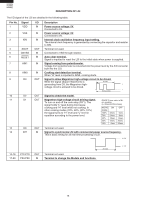
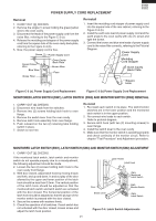
R-209(IN) R-209(W) R-209(Y) DESCRIPTION OF LSI The I/O signal of the LSI are detailed in the following table. Pin No. Signal 1 VDD 2 VSS 3 XIN 4 XOUT 5 CNVSS 6 RESET 7 AIN1 8 AIN0 9 D3 I/O IN IN IN OUT IN IN IN IN OUT Description Power source voltage: 5V. Connected to 5V. Power source voltage: 0V. Connected to 0V. Internal clock oscillation frequency input setting. The internal clock frequency is generated by connecting the capacitor and resistor to XIN. Terminal not used. Connected to VSS through resistor. Auto clear terminal. Signal is inputted to reset the LSI to the initial state when power is supplied. Signal coming from potentiometer. Voltage from potentiometer is converted into the power level by the A/D converter built into the LSI. Cooking start detection terminal. When "H" level is inputted to AIN0, cooking starts. Signal to allow Magnetron high-voltage circuit to be drived. While the signal (Sqrare Waveform) is 20 msec generating from D3, the Magnetron high- H voltage circuit is allowed to be drived. L During cooking 10 D2 OUT Signal to check the model. 11 D1 OUT Magnetron high-voltage circuit driving signal. ON/OFF time ratio in Mi- To turn on and off the cook relay (RY1). The cro cooking signal holds "L" level during microwave (a. 32second time base) cooking and "H" level while not cooking. In MICRO ON OFF other cooking modes (70%, 50%, 30%, 10%) COOK the signal turns to "H" level and "L" level in 100% 32sec. 0sec. repetition according to the power level. 70% 24sec. 8sec. 50% 18sec. 14sec. 30% 12sec. 20sec. 10% 6sec. 26sec. 12 D0 OUT Terminal not used. 13 INT IN Signal to synchronize LSI with commercial power source frequency. This is basic timing for all real time processing of LSI. H : 5V 20 msec L : 0V 14-16 17-20 P12-P10 P03-P00 OUT IN Terminal not used. Terminal to change the Models and functions. 16
-
 1
1 -
2
-
3
-
4
-
5
-
6
-
7
-
8
-
9
-
10
-
11
-
12
-
 13
13 -
 14
14 -
 15
15 -
 16
16 -
 17
17 -
 18
18 -
 19
19 -
 20
20 -
 21
21 -
 22
22 -
 23
23 -
24
-
25
-
26
-
27
-
28
-
29
-
30
-
31
-
32
-
33
-
34
-
35
-
36
 |
 |
