Sharp XL-HP500 Operation Manual - Page 6

General Information - xl hp500w

Page 6 highlights

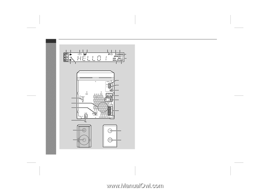
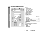
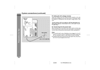
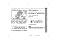
XL-HP500W Controls and indicators (continued) ENGLISH 1 2 34 5 6 78 9 10 11 12 13 14 15 General Information 5 6 7 8 1 9 2 3 10 4 1 3 2 4 E-5 " Display 1. Disc Number Indicators 2. CD Play Indicator 3. Tape Reverse Mode Indicator 4. Tape Reverse Play Indicator 5. Tape Forward Play Indicator 6. FM Stereo Mode Indicator 7. FM Stereo Receiving Indicator 8. Memory Indicator 9. Extra Bass Indicator 10. Timer Recording Indicator 11. Timer Play Indicator 12. CD Pause Indicator 13. CD Repeat Play Indicator 14. Tape Record Indicator 15. Sleep Indicator " Rear panel Reference page 1. AC Voltage Selector 9 2. Cooling Fan 3. Subwoofer Output Socket 28 4. AC Power Lead 7, 9 5. FM 75 Ohms Aerial Terminal 7, 8 6. FM Aerial Earth Terminal 7, 8 7. AM Loop Aerial Socket 7, 8 8. Video/Auxiliary (Audio Signal) Input Sockets 27 9. Span Selector Switch 10 10. Speaker Terminals 7, 8 Note: This product is equipped with a cooling fan inside, which begins to run at a specified volume level for better heat radiation. " Speaker system 1. Tweeter 2. Woofer 3. Bass Reflex Duct 4. Speaker Terminals 02/8/6 XL-HP500W(A)1.fm

  • 1
  • 2
  • 3
  • 4
  • 5
  • 6
  • 7
  • 8
  • 9
  • 10
  • 11
  • 12
  • 13
  • 14
  • 15
  • 16
  • 17
  • 18
  • 19
  • 20
  • 21
  • 22
  • 23
  • 24
  • 25
  • 26
  • 27
  • 28
  • 29
  • 30
  • 31
  • 32
  • 33
  • 34
  • 35
  • 36

02/8/6
XL-HP500W(A)1.fm
E-5
ENGLISH
XL-HP500W
General Information
Controls and indicators (continued)
"
Display
1. Disc Number Indicators
2. CD Play Indicator
3. Tape Reverse Mode Indicator
4. Tape Reverse Play Indicator
5. Tape Forward Play Indicator
6. FM Stereo Mode Indicator
7. FM Stereo Receiving Indicator
8. Memory Indicator
9. Extra Bass Indicator
10. Timer Recording Indicator
11. Timer Play Indicator
12. CD Pause Indicator
13. CD Repeat Play Indicator
14. Tape Record Indicator
15. Sleep Indicator
"
Rear panel
Reference page
1. AC Voltage Selector . . . . . . . . . . . . . . . . . . . . . . . . . . . . . . . . 9
2. Cooling Fan
3. Subwoofer Output Socket . . . . . . . . . . . . . . . . . . . . . . . . . . 28
4. AC Power Lead . . . . . . . . . . . . . . . . . . . . . . . . . . . . . . . . . . 7, 9
5. FM 75 Ohms Aerial Terminal . . . . . . . . . . . . . . . . . . . . . . . 7, 8
6. FM Aerial Earth Terminal . . . . . . . . . . . . . . . . . . . . . . . . . . 7, 8
7. AM Loop Aerial Socket
. . . . . . . . . . . . . . . . . . . . . . . . . . . 7, 8
8. Video/Auxiliary (Audio Signal) Input Sockets . . . . . . . . . . 27
9. Span Selector Switch . . . . . . . . . . . . . . . . . . . . . . . . . . . . . . 10
10. Speaker Terminals . . . . . . . . . . . . . . . . . . . . . . . . . . . . . . . 7, 8
Note:
This product is equipped with a cooling fan inside, which begins to
run at a specified volume level for better heat radiation.
"
Speaker system
1. Tweeter
2. Woofer
3. Bass Reflex Duct
4. Speaker Terminals
2
3
1
4
5
6
7
8
9
10
2
1
345
6
78
9
10
11
15
14
12 13
3
4
1
2