Sharp XR-30XDM Operation Manual - Page 57
Connecting Pin Assignments
 |
View all Sharp XR-30XDM manuals
Add to My Manuals
Save this manual to your list of manuals |
Page 57 highlights
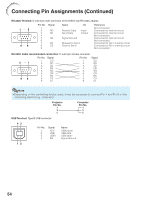
Connecting Pin Assignments COMPUTER/COMPONENT input and COMPUTER/COMPONENT output Terminals:mini D-sub 15 pin female connector COMPUTER Input/Output Pin No. Signal 1. Video input (red) 11 15 2. Video input (green/sync on green) 3. Video input (blue) 4. Not connected 5. Not connected 6. Earth (red) 7. Earth (green/sync on green) 8. Earth (blue) 1 6 5 10 9. Not connected 10. GND 11. Not connected 12. Bi-directional data 13. Horizontal sync signal: TTL level 14. Vertical sync signal: TTL level 15. Data clock COMPONENT Input/Output Pin No. Signal 1. PR (CR) 2. Y 3. PB (CB) 4. Not connected 5. Not connected 6. Earth (PR) 7. Earth (Y) 8. Earth (PB) 9. Not connected 10. Not connected 11. Not connected 12. Not connected 13. Not connected 14. Not connected 15. Not connected DVI-D Terminal: 24 pin connector 24 17 8 1 16 9 Pin No. Signal 1. T.M.D.S data 2- 2. T.M.D.S data 2+ 3. T.M.D.S data 2 shield 4. Not connected 5. Not connected 6. DDC clock 7. DDC data 8. Not connected 9. T.M.D.S data 1- 10. T.M.D.S data 1+ 11. T.M.D.S data 1 shield 12. Not connected 13. Not connected 14. +5V power 15. Ground Pin No. Signal 16. Hot plug detection 17. T.M.D.S data 0- 18. T.M.D.S data 0+ 19. T.M.D.S data 0 shield 20. Not connected 21. Not connected 22. T.M.D.S clock shield 23. T.M.D.S clock+ 24. T.M.D.S clock- RS-232C Terminal: mini DIN 9 pin female connector 9 6 5 8 2 1 Pin No. 1. 7 2. 3. 4. 3 5. 6. 7. 4 8. 9. Signal RD SD SG RS CS Name I/O Receive Data Send Data Input Output Signal Ground Request to Send Clear to Send Reference Not connected Connected to internal circuit Connected to internal circuit Not connected Connected to internal circuit Not connected Connected to CS in internal circuit Connected to RS in internal circuit Not connected Appendix 53
-
 1
1 -
2
-
3
-
4
-
5
-
6
-
7
-
8
-
9
-
10
-
11
-
12
-
13
-
14
-
15
-
16
-
17
-
18
-
19
-
20
-
21
-
22
-
23
-
24
-
25
-
26
-
27
-
28
-
29
-
30
-
31
-
32
-
33
-
34
-
35
-
36
-
37
-
38
-
39
-
40
-
41
-
42
-
43
-
44
-
45
-
46
-
47
-
48
-
49
-
50
-
51
-
 52
52 -
 53
53 -
 54
54 -
 55
55 -
 56
56 -
 57
57 -
 58
58 -
 59
59 -
 60
60 -
 61
61 -
 62
62 -
63
-
64
-
65
-
66
-
67
-
68
-
69
-
70
-
71
 |
 |
