Sharp XR-30XDM Operation Manual - Page 58
Connecting Pin Assignments Continued
 |
View all Sharp XR-30XDM manuals
Add to My Manuals
Save this manual to your list of manuals |
Page 58 highlights
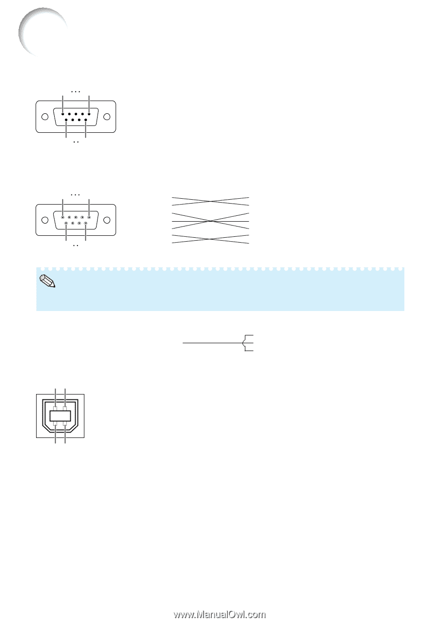
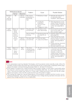
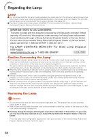
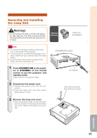
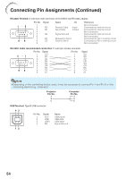
Connecting Pin Assignments (Continued) RS-232C Terminal: D-sub 9 pin male connector of the DIN-D-sub RS-232C adaptor 1 5 69 Pin No. 1. 2. 3. 4. 5. 6. 7. 8. 9. Signal RD SD SG RS CS Name I/O Receive Data Send Data Input Output Signal Ground Request to Send Clear to Send Reference Not connected Connected to internal circuit Connected to internal circuit Not connected Connected to internal circuit Not connected Connected to CS in internal circuit Connected to RS in internal circuit Not connected RS-232C Cable recommended connection: D-sub 9 pin female connector Pin No. Signal Pin No. Signal 5 1 96 1. CD 2. RD 3. SD 4. ER 5. SG 6. DR 7. RS 8. CS 9. CI 1. CD 2. RD 3. SD 4. ER 5. SG 6. DR 7. RS 8. CS 9. CI Note • Depending on the controlling device used, it may be necessary to connect Pin 4 and Pin 6 on the controlling device (e.g. computer). Projector Pin No. 4 5 6 Computer Pin No. 4 5 6 USB Terminal: Type B USB connector 43 Pin No. 1. 2. 3. 4. Signal VCC USB- USB+ SG Name USB power USB data- USB data+ Signal Ground 12 54
-
 1
1 -
2
-
3
-
4
-
5
-
6
-
7
-
8
-
9
-
10
-
11
-
12
-
13
-
14
-
15
-
16
-
17
-
18
-
19
-
20
-
21
-
22
-
23
-
24
-
25
-
26
-
27
-
28
-
29
-
30
-
31
-
32
-
33
-
34
-
35
-
36
-
37
-
38
-
39
-
40
-
41
-
42
-
43
-
44
-
45
-
46
-
47
-
48
-
49
-
50
-
51
-
52
-
 53
53 -
 54
54 -
 55
55 -
 56
56 -
 57
57 -
 58
58 -
 59
59 -
 60
60 -
 61
61 -
 62
62 -
 63
63 -
64
-
65
-
66
-
67
-
68
-
69
-
70
-
71
 |
 |