Sony BVME250 User Manual
Sony BVME250 Manual
 |
View all Sony BVME250 manuals
Add to My Manuals
Save this manual to your list of manuals |
Sony BVME250 manual content summary:
- Sony BVME250 | User Manual - Page 1
PROFESSIONAL VIDEO MONITOR BVM-E250 OPERATION MANUAL [English] 1st Edition (Revised 2) - Sony BVME250 | User Manual - Page 2
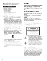
manual thoroughly and retain it for future reference. Important Safety Instructions • Read these instructions. • Keep these instructions. • Heed all warnings. • Follow all instructions of important operating and maintenance (servicing) instructions in the literature accompanying the appliance - Sony BVME250 | User Manual - Page 3
expressly approved in this manual could void your authority service personnel. For the customers in Canada This Class A digital Sony Deutschland GmbH, Hedelfinger Strasse 61, 70327 Stuttgart, Germany. For any service or guarantee matters please refer to the addresses given in separate service - Sony BVME250 | User Manual - Page 4
, Minato-ku, Tokyo, 108-0075 Japon. Le représentant autorisé pour EMC et la sécurité des produits est Sony Deutschland GmbH, Hedelfinger Strasse 61, 70327 Stuttgart, Allemagne. Pour toute question concernant le service ou la garantie, veuillez consulter les adresses indiquées dans les documents de - Sony BVME250 | User Manual - Page 5
Kundendienst- oder Garantiedokumenten aufgeführten Anschriften. Dieser Apparat darf nicht im Wohnbereich verwendet werden. WARNUNG 1. Verwenden Sie ein geprüftes Netzkabel (3-adriges Stromkabel)/einen geprüften Geräteanschluss/einen geprüften Stecker mit Schutzkontakten entsprechend den - Sony BVME250 | User Manual - Page 6
Supported 25 Turning on the Monitor 25 Settings 26 Selecting the Area 26 Setting for the LAN to Connect the Multiple Units 27 Selecting the Monitor (Designation of the Monitor or Group ID Number 28 Assigning the Input Signal to the Channel.........28 Setting the Display Mode of the Picture - Sony BVME250 | User Manual - Page 7
to Another Monitor 94 Displaying the Monitor Status Page 95 Assigning a Function to a Function Button 97 Upgrading the Monitor and Controller...........98 Modification Frequency 116 Picture Display Size 118 Picture Frame Display 120 Scan Mode Image 122 Troubleshooting 124 Dimensions 126 - Sony BVME250 | User Manual - Page 8
recommended for service operation. spontaneously. These problems are not a monitor's screen. This may cause the screen to lose uniformity. • The screen and the cabinet become warm during operation. This is not a malfunction. On Burn-in Due to the characteristics of the material used in the OLED - Sony BVME250 | User Manual - Page 9
details, refer to the operation manual of the connected equipment. • Use Due to an OLED's panel structure and of an image smaller than the monitor screen, such as in a Sony dealer. If you have any questions about this unit, please contact your Sony service representative. 9 Precautions - Sony BVME250 | User Manual - Page 10
in Software Version 1.1 The following new functions are supported for Version 1.1 of the BVM-E250. Menu Supported function Reference page • Copy From1) (in the Picture Adj menu of the Adjustment menu) (in the Color Temp Adj menu of the Adjustment menu) (in the Channel Configuration menu - Sony BVME250 | User Manual - Page 11
" decreases the viewing difference that occurs due to the individuality of each panel. Also, the BVM-E250 realizes the high picture quality and high-trust required for the master monitor by the color management system with its wide color gamut device, high-resolution/precise gradation display - Sony BVME250 | User Manual - Page 12
mask of the 5% over scan portion in the normal scan) for the picture display. The monitor is equipped with a native scan display function which maps the pixel of the input adaptor (BKM-250TG). 3D signal analyzing function The monitor supports the following display modes of the 3D signal analyzing - Sony BVME250 | User Manual - Page 13
supported with software version 1.1 or higher, and require special third-party software. For details, contact your Sony prevent burn-in. Variable picture adjustment functions Auto chroma, monitor during production of digital cinemas, recorded television shows, and commercials. You can view the camera - Sony BVME250 | User Manual - Page 14
The BKM-16R is a controller of the BVM-E250 and you can control multiple monitors from one controller. In this manual, the BKM-16R is referred to as the controller. For installation BKM-37H/BKM-38H Controller Attachment Stand Used to join a BKM-16R and the BVM-E250. Using the BKM-37H, you can adjust - Sony BVME250 | User Manual - Page 15
Chapter 1 Overview Input/Output Connectors and Input Adaptors This monitor is equipped with two 3G/HD/SD-SDI input connectors, an HDMI input connector, and a DisplayPort input connector for the standard interface. In this manual, these connectors are referred to as the standard input. By adding - Sony BVME250 | User Manual - Page 16
be put into operation mode. Wait until the lamp is steadily lit. • When the OPERATE lamp is flashing in green, the monitor is not in full operation mode and images cannot be displayed correctly. Wait until the lamp is steadily lit in green. The OPERATE lamp may - Sony BVME250 | User Manual - Page 17
lamp, OPERATE lamp and/or ECO lamp on the front panel may show an error or warning while the monitor is being operated. If the error or warning is shown, please contact your Sony representative. Error display ECO lamp Lights in yellow Lights in yellow OVER RANGE lamp Lights in amber Flashes - Sony BVME250 | User Manual - Page 18
, optional). CAUTION • For safety, do not connect the connector for peripheral device wiring that might have excessive voltage to this port. Follow the instructions for this port. • When you connect the LAN cable of the unit to peripheral device, use a shielded-type cable to prevent malfunction due - Sony BVME250 | User Manual - Page 19
to display high quality digital picture. The HDMI specification supports HDCP (High-bandwidth Digital Content Protection), a copy protection technology that incorporates coding technology for digital video signals. Notes • The HDMI audio signal is not available for this monitor. • Use HDMI compliant - Sony BVME250 | User Manual - Page 20
the input adaptor with serial number 7300001 or higher. Caution To reduce the risk of electric shock, turn off the MAIN POWER switch of the monitor and disconnect the AC power cord before installing or removing adaptors. 20 Environments of the Installation Location / Installing an Input Adaptor - Sony BVME250 | User Manual - Page 21
or OPTION 3 and 4 option ports. Example of Dual-link cable connection 3 Push the adaptor in until it is firmly fit into the connector inside the monitor, then tighten the two screws to secure the adaptor. INPUT 1 INPUT 2 INPUT 1 INPUT 2 OPTION 1 and 2 OPTION 3 and 4 21 Installing an Input Adaptor - Sony BVME250 | User Manual - Page 22
INPUT 2. Attaching the Bracket INPUT 1 You can prevent falling of the monitor by using the supplied bracket. 1 Remove three screws from the bracket signal to INPUT 2. 2 Attach the bracket on the rear panel of the monitor with the three removed screws. 22 Attaching the Bracket 3 Attach a piece - Sony BVME250 | User Manual - Page 23
When an optional LAN cable is connected, use a shielded-type cable to prevent a malfunction due to noises. 4 Connect the DC 5V OUT connector of the monitor and the DC 5V/12V IN connector of the controller by using the SMF-700 or the cable supplied with the BKM-37H/ 38H. Or - Sony BVME250 | User Manual - Page 24
When the multiple units are connected, set for the LAN before setting the NETWORK switch to LAN (page 27). 4 Set the NETWORK switches of each monitor and the controller to LAN. Chapter 2 Preparations AC adaptor (supplied with the BKM-16R) Switching hub (recommended: with AUTO MDI/MDI-X function - Sony BVME250 | User Manual - Page 25
POWER switch on the left side panel to turn on the power. When you turn on the monitor for the first time after purchasing it, the Select Area screen is displayed. Select the area where you intend to use this monitor. For selecting the area, see page 26. 25 Turning on the Power - Sony BVME250 | User Manual - Page 26
BT.709 ENTER button UP/DOWN buttons Ent button 1 Turn on the monitor with the MAIN POWER switch. The Select Area screen appears. Select Area North button of the controller to select the area where you intend to use the monitor and press the ENTER (Ent) button. If you select either Latin America - Sony BVME250 | User Manual - Page 27
Area B PAL Area B NTSC area PAL area Customers who will use this monitor in the shaded areas shown in the map below should select NTSC Area. to PEER TO PEER. 2 Set the different IP address to each monitor and the controller. Monitor: Set the IP address in the Network Setting menu (page 68) - Sony BVME250 | User Manual - Page 28
or group ID number. 3 Press the ENTER or Ent button to confirm the setting. The monitor ID number, group ID number or ALL is displayed in the display window. Notes • When the monitor with no assigned monitor ID number or group ID number is selected, the setting is not changed and the previous - Sony BVME250 | User Manual - Page 29
digit channel number. 2 Set the input signal for the selected channel in Channel Configuration menu (page 48). The required setting is different due to the input signal or picture quality signal. To measure the signal accurately, the monitor must be calibrated correctly using a reference signal. - Sony BVME250 | User Manual - Page 30
the manual adjustment of chroma and phase to adjust them further after automatic adjustment or to adjust the digital signal from monitor. 2 Select Auto in the Picture Adj menu of the Adjustment menu and perform the automatic adjustment of the chroma, phase and matrix in Auto Adjust (page 43). Manual - Sony BVME250 | User Manual - Page 31
format color-bar signal or SMPTE color-bar signal to the monitor. The following are explained as the example when the multi format color-bar signal is used for adjustment. 2 Select the Manual Adjust menu (page 44) in the Picture Adj menu of the Adjustment menu. 3 Adjust the -2%, 0% and +2% ranges or - Sony BVME250 | User Manual - Page 32
MENU button 3 ENTER button 4 PHASE knob PHASE CHROMA BRIGHT CONTRAST MANUAL MANUAL MANUAL MANUAL REMOTE SINGLE 1 GROUP 4 ALL SINGLE GROUP ALL 7 INPUT the upper level. (On the main menu, goes back to the normal picture.) 3 ENTER button Changes the item. In setting mode, confirms the - Sony BVME250 | User Manual - Page 33
of the menu screen. iChannel Configuration CH01 Format B Input Port: xxxxx Input No: xxxxx Screen Aspect B Sync Mode: xxx 1/3 v V Color Temp: Picture Preset: Matrix Color Profile xxx xxxxx B B When you select one item on the main menu, the level 1 menu of the selected item appears - Sony BVME250 | User Manual - Page 34
: xxxxx Screen Aspect B Sync Mode: xxx 1/3 v V Color Temp: Picture Preset: Matrix Color Profile xxx xxxxx B B Set: ENTER Cancel: MENU Ent button. The cursor moves to the setting value and the monitor enters in setting mode. Display example iChannel Configuration CH01 Marker Preset - Sony BVME250 | User Manual - Page 35
side of the cursor is deleted. Entering the Channel Number When selecting a one-digit number, press the button of the channel number. When selecting a two-digit number, first press the 0 button, then press a two-digit channel number. Channel numbers 91 to 97 assignment The signal systems to which - Sony BVME250 | User Manual - Page 36
Main menu Level 1 Level 2 Adjustment Picture Adj Auto Color Temp Adj Position Adj Manual Adjust Copy From Manual Copy From Restore Factory Data H Monitor Memory Stick Manual Adjust Original Value Signal Contrast/Bright Hold Preset Value Other Monitor Memory Stick Level 4 Monitor ID Monitor - Sony BVME250 | User Manual - Page 37
Format Input Port Input No Screen Aspect Sync Mode Color Temp Picture Preset Matrix Color Profile Marker Preset H Shift Offset Channel Name /DisplayPort Auto 24PsF 25PsF/50I 30PsF/60I Other CH Other Monitor Memory Stick Level 3 Monitor ID Auxiliary Setting menu (page 55) Main menu Auxiliary - Sony BVME250 | User Manual - Page 38
Bright Area Marker 2 Aspect Mode Aspect Area Size Width Height Mode Thickness Color Bright Center Marker Mode Color Bright Preset Value Other Monitor Memory Stick Line Display Line Color Line Bright Line Display Line Color Line Bright Position Line Display Line Color Line Bright Position Blending - Sony BVME250 | User Manual - Page 39
Chapter 3 Menu Main menu Level 1 Gamut Error Display 3D Setting Capture Internal Signal Function Switch Level 2 Gamut Error Display OSD Notification OSD Notification Reset Input Detection Post-Process Detection Zebra Pattern Horopter Check Load Rename Delete Level 3 Detection Pixel Threshold - Sony BVME250 | User Manual - Page 40
Password Date/Time Scan Mode Skip Screen Saver Monitor Upgrade Maintenance Software Upgrade Kernel Upgrade FPGA Broadcast SDAP Broadcast Period Acceptable IP Address Reset Protocol Setting Format Position CH No Position CH Name Position Scan Mode Position Closed Caption Type Service 708 Service - Sony BVME250 | User Manual - Page 41
Maintenance Level 2 Memory Stick Other Monitor Memory Stick Memory Stick Back Up System Data Restore System Data Level 3 Monitor ID Level 4 System Status menu Serial No Payload ID Video Standard Sampling Structure Bit Depth Picture Rate Scanning Method Link Number Current Status Format I/PsF/P - Sony BVME250 | User Manual - Page 42
1 Network Level 2 Network Setting SNMP Setting Protocol Setting Function Key Monitor ID Display Controller Upgrade F1 - F16 Software Upgrade Kernel Upgrade Level /SDAP Community SDCP Port No SDAP Port No SDAP Broadcast SDAP Broadcast Period Reset Protocol Setting Level 4 Mode Trap Address - Sony BVME250 | User Manual - Page 43
is set to On • When Butterfly is set to On • When Blending is set to On Chapter 3 Menu Menu Function and Operation Menu Picture Adj Auto Auto Adjust Function and operation ([ ]: factory setting) Adjusts the chroma, phase, matrix and signal level automatically and contrast, brightness, chroma and - Sony BVME250 | User Manual - Page 44
Chapter 3 Menu Picture Adj Menu Color Bar Restore Factory Data Status Input Port Format Matrix Manual Adjust Copy From Preset Value Other Monitor Monitor ID Memory Stick Function and operation ([ ]: factory setting) Sets the color-bar signal to input. [Full Field 8]: 100% full-field 8-color bars - Sony BVME250 | User Manual - Page 45
picture preset data Preset1 to Preset5 or Preset (D-Cine) set in the Picture Preset menu of the Channel Configuration menu. To change the type of the picture Blue together): CONTRAST knob To hide the characters on the monitor during manual adjustment Set the CHAR OFF button of the controller to on - Sony BVME250 | User Manual - Page 46
Copies the other color temperature. Note Use the controller with software version 1.6 or higher to use the Copy From function. Copies other data in this monitor. Except for the XYZ format signal When the item is selected, you can select from D93, D65, D61, D55, D-Cine, User1, User2, User3, User4 or - Sony BVME250 | User Manual - Page 47
button. Cancel: To cancel, press the MENU button. Adjusts the position of the picture when the analog signal is input. When the item is selected, the signal system from the BKM-229X is displayed. To hide the characters on the monitor during adjustment Set the CHAR OFF button of the controller to on. - Sony BVME250 | User Manual - Page 48
is 3G/HD/SD-SDI Auto. Sets the serial digital signal format (Single-link 3G-SDI, HD-SDI or according to the Sampling Structure, Bit Depth, Picture and transport scanning method information for Payload ID and the signal format status of the current monitor in "SDI Payload ID Status" (page 77 - Sony BVME250 | User Manual - Page 49
format to be displayed, see page 114. Sets the DisplayPort signal format. In this manual, the 800 × 600, 1024 × 768, 1280 × 960, 1280 × 1024 and Option4, Option1&2 or Option3&4. Standard When using the standard SDI input of the monitor • When Format is set to 3G/HD/SD-SDI Auto or 4:2:2 YCbCr 10bit - Sony BVME250 | User Manual - Page 50
Aspect HD SD DC 2048 × 1080 HDMI Auto Sync Mode Color Temp Picture Preset Function and operation ([ ]: factory setting) Option1&2, Option3&4 • the aspect ratio of the digital cinema signal (2048 × 1080). You can select from [1.896:1] or 2.39:1. Sets the manual or automatic setting for the aspect - Sony BVME250 | User Manual - Page 51
240M. Sets the manual or automatic setting for the transmission matrix of the HDMI or DisplayPort signal. Off: Select to use Matrix set in the HD or SD menu. [On]: Select to set Matrix automatically according to the input signal. As the BVM-E250 is equipped with a wider color space OLED panel, the - Sony BVME250 | User Manual - Page 52
BVM-E250. S-GAMUT/S-LOG: Displays with the color space of the transmission gamma S-LOG and the wide color space mode S-GAMUT, which is available for the output signal of F23 or F35 Digital Cinematography Camera CRT BVM: Gamma curve of the BVM-D or BVM-A series 2.2: Gamma curve 2.2 2.4: Monitor gamma - Sony BVME250 | User Manual - Page 53
picture. To display the characters, set the CHAR OFF button to off. Sets a channel name. When the item is selected, you can select a preset name, or enter a new one. PROG: Program signal EDIT: Signal from an editor CAM: Camera signal VTR: Signal from a VTR PREV: Preview monitor the manual or - Sony BVME250 | User Manual - Page 54
25PsF/50I 30PsF/60I Film Cadence Copy From Other CH Other Monitor Monitor ID Memory Stick Function and operation ([ ]: factory setting) When this is not selectable. When the item is selected, you can designate the source monitor. When the ID number is entered, you can designate the channel to be - Sony BVME250 | User Manual - Page 55
Menu Overview This menu is used for setting the monitor condition such as the aperture modification and decode . When the brightness or contrast is increased, using the brightness or contrast adjustment, the picture may be clipped, because of the dynamic range of the circuit. Sets whether or not - Sony BVME250 | User Manual - Page 56
(page 52) of the Channel Configuration menu. To hide the characters on the monitor during setting Set the CHAR OFF button of the controller to on. As the characters on the display are hidden, it becomes easy to adjust the picture. To display the characters, set the CHAR OFF button to off. Sets - Sony BVME250 | User Manual - Page 57
Chapter 3 Menu Marker Setting Menu Bright Blanking Area Marker 1 Area Marker 1 Aspect Mode Aspect Area Size Width Height Mode Function and operation ([ ]: factory setting) Sets the luminance of the aspect marker. You can select from High (bright) or [Low] (dark). Sets the blanking outside the - Sony BVME250 | User Manual - Page 58
Setting Menu Thickness Color Bright Area Marker 2 Center Marker Center Marker Mode Color Bright H Position V Position Copy From Preset Value Other Monitor Monitor ID Memory Stick P&P Setting Side by Side Line Display Function and operation ([ ]: factory setting) With 4:3 80% 80% Aspect Mode 16 - Sony BVME250 | User Manual - Page 59
Zoom Setting Line Color Gamut Error Display Gamut Error Display Function and operation ([ ]: factory setting) Sets the boundary line color of two pictures. You can select from [White] (white), Red (red), Green (green), Blue (blue), Yellow (yellow), Cyan (cyan), Magenta (magenta) or Black (black - Sony BVME250 | User Manual - Page 60
the error is detected ([Off] or On). Sets the method to reset the error detection mode. [Auto]: Resets automatically after detecting the error. Manual: Resets manually. To reset the error detection, select Error Notify Clear (page 66) in the Function Switch menu of the Function Setting menu or set - Sony BVME250 | User Manual - Page 61
mode. Red: Displays only the red component of the video signal. Blue: Displays only the blue component of the video signal. Captures the still picture for the standard of the color evaluation (HD Frame Capture). Note Use the controller with software version 1.6 or higher to use the HD Frame Capture - Sony BVME250 | User Manual - Page 62
.) Sets whether or not to display the aspect in 16:9 or 1.896:1 (digital cinema signal) (Off or [On]). Notes • The aspect ratio is not selectable or On). When the 720/24, 25, 30P signal is input, the display position is changed with the PHASE knob. Notes • The picture is not displayed in H delay - Sony BVME250 | User Manual - Page 63
be displayed is synchronized with the sync signal included in the signals being monitored (Internal Sync). Notes • When Component is set to YPbPr or On). Notes • Set Native Scan to On for the interlace display. • The picture is not displayed in interlace mode in the following cases: - When Side by - Sony BVME250 | User Manual - Page 64
Chapter 3 Menu Function Switch Menu Marker Aspect Marker Area Marker 1 Area Marker 2 Center Marker Function and operation ([ ]: factory setting) Sets whether or not to display all markers ([Off] or On). Notes • The marker is not displayed in the following cases: - When the input signal has no - Sony BVME250 | User Manual - Page 65
Chapter 3 Menu Function Switch Menu Aspect Marker-Line Aspect Blanking-Half Aspect Blanking-Black Side by Side Wipe Butterfly Blending Function and operation ([ ]: factory setting) Sets whether or not to display the line of the aspect marker ([Off] or On). Notes • The line of the aspect marker is - Sony BVME250 | User Manual - Page 66
Chapter 3 Menu Function Switch Menu Error Notify Clear Audio Level Meter ALM Hold Reset Time Code Difference Checkerboard Function and operation ([ ]: factory setting) When the item is selected, the notification of the gamut error detection (OSD Notification) is cleared. Note The Error Notify - Sony BVME250 | User Manual - Page 67
Chapter 3 Menu Function Switch Menu L/R Switch Horopter Check Flip H Function and operation ([ ]: factory setting) Sets whether or not to display either the left and right 3D video signals on the screen by switching them alternately ([Off] or On). This item is available for dual-stream HD-SDI - Sony BVME250 | User Manual - Page 68
and operation ([ ]: factory setting) Sets the remote control function of the network. Enter a monitor ID number. Set to 01 to 99. [01] Enter a group ID number. Set to enter the community name (four characters). SONY: SONY is entered as a community name. New Name: Enter a new name. 68 - Sony BVME250 | User Manual - Page 69
Menu SDCP Port No SDAP Port No SDAP Broadcast SDAP Broadcast Period Acceptable IP Address Reset Protocol Setting Parallel Up, Interlace Tally: The function to turn on the tally lamp Power Off: The monitor power function Parallel Remote (3/5) Marker, Aspect Marker, Area Marker 1, Area Marker 2, - Sony BVME250 | User Manual - Page 70
set to 3G/HD/SD-SDI Auto (page 48) in the Channel Configuration menu, and the Picture Rate information for the Payload ID is 23.98, 29.97 or 59.94, even if the monitor determines the picture rate as 24 Hz, 30 Hz or 60 Hz. For details on Payload ID, see - Sony BVME250 | User Manual - Page 71
Service when Type is set to 708. You can select from Service1 to Service6. [Service1] Sets Service scan mode setting of the monitor. Sets the audio channel. about 1 second. Manual Reset: The peak hold is released manually. To release for the menu. Enter a four-digit number for the password. [9999] - Sony BVME250 | User Manual - Page 72
Chapter 3 Menu Password Menu Apply Password Adjustment Channel Configuration Auxiliary Setting Function Setting System Configuration Individual Item Network Parallel Remote Power On Screen Set Date/Time Scan Mode Skip Screen Saver File Management Controller Key Protect Date/Time Year Month Day - Sony BVME250 | User Manual - Page 73
menu. For details on upgrading the monitor, see "Upgrading the Monitor and Controller" on page 98. Upgrades the software for the monitor. Upgrades the kernel of the monitor. Upgrades the FPGA data of the monitor. The menu for the Sony service representative is displayed. Chapter 3 Menu 73 - Sony BVME250 | User Manual - Page 74
. Enter the ID number of the source monitor. When the NETWORK switch is set to PEER TO PEER, this is not selectable. When the ID number is entered, you can select the data to be copied. All: Copies all data. Picture Preset: Copies the picture preset data. Color Temp: Copies the color temperature - Sony BVME250 | User Manual - Page 75
select the data to be copied. All: Copies all data. Picture Preset: Copies the picture preset data. Color Temp: Copies the color temperature data. CH is selected, the following message appears. All data will be restored and monitor will restart Are you sure? OK: To continue, press the ENTER (Ent - Sony BVME250 | User Manual - Page 76
Overview This menu is used to view general data about the monitor status, current channel, etc. When System Status is selected, -250TG is installed Empty: When the adaptor is not installed Unknown: When non-supported adaptor is installed When the item is selected, the model name and serial number - Sony BVME250 | User Manual - Page 77
data superimposed on the SDI signal and current signal status of the monitor. When the option port number in which the BKM-250TG is Depth: Decode display of Byte 4_Bit 1-0 (8bit/10bit/12bit) Picture Rate: Decode display of Byte 2_Bit 3-0 (23.98/24/25/29.97/30/50/59.94/60) Scanning Method: Decode - Sony BVME250 | User Manual - Page 78
to the function button of the controller. When Controller is selected, the following menu is displayed. iController Network B Function Key B Monitor ID Display: xxx Controller Upgrade B Chapter 3 Menu Menu Function and Operation Menu Network Network Setting IP Address Subnet Mask Default - Sony BVME250 | User Manual - Page 79
Community SDCP Port No SDAP Port No SDAP Broadcast SDAP Broadcast Period Reset Protocol Setting Function Key Function and settings to send information manually or automatically ([Manual] or Auto). This item cannot be selected when the monitor is controlled with BKM-15R or BVM-A14F5. Sets the IP - Sony BVME250 | User Manual - Page 80
picture. Native Scan: Displays the picture in native scan mode. 16:9: Changes the aspect ratio to 16:9 or 1.896:1 (digital monitor screen hide during manual adjustment. Color Temp: You can access directly the Manual monochrome picture is displayed. When the button is set to off, the monitor switches - Sony BVME250 | User Manual - Page 81
Chapter 3 Menu Function Key Menu Monitor ID Display Function and operation ([ ]: factory setting) Area Marker1: An Mode to a function button of the controller. Degauss: The CRT is degaussed (only for BVM-A series). Sets display mode of the display window. [On]: Always displayed. Auto: Displayed - Sony BVME250 | User Manual - Page 82
selected, the screen for inputting the password is displayed. After the 4-digit password is entered, the current versions of Software Version and Kernel menu. For details on upgrading the controller, see "Upgrading the Monitor and Controller" on page 98. Upgrades the software for the controller - Sony BVME250 | User Manual - Page 83
Protect Function and operation ([ ]: factory setting) Sets the key protection. On: The button on the controller (except the menu operation buttons and monitor selection buttons) and the parallel remote do not function and other settings are not changeable. [Off]: Release the lock. 83 Key Protect - Sony BVME250 | User Manual - Page 84
according to the input signal or the object to evaluate the picture. Interlace display mode: The picture is displayed in interlace mode without I/P conversion processing. The picture near the original quality of the input signal is monitored. Notes • When a 1080/241) P (PsF) or 1080/25P (PsF) input - Sony BVME250 | User Manual - Page 85
input (The native scan is displayed regardless of the setting.) • When a digital cinema signal (2048 × 1080) is input and the internal signal is displayed position to the center by pressing the MANUAL button of PHASE of the controller. Displayed by sliding the picture with the PHASE knob of the - Sony BVME250 | User Manual - Page 86
Mode You can select scan mode from a native scan, under scan (-3%), normal scan (0%) and over scan (mask of 5% over scan portion in the normal scan picture). You can set scan mode with the NATIVE SCAN button or SCAN button of the controller, or in the Function Switch menu of the Function - Sony BVME250 | User Manual - Page 87
Chapter 4 Operations Displaying Two Signals on One Screen (Picture&Picture) Butterfly (butterfly) The right picture is a left-right reversal picture of the left picture. Two input signals are output on the monitor. You can select the display mode from Side by Side (side by side), Wipe (wipe), - Sony BVME250 | User Manual - Page 88
button1) of the controller or in the Function Switch menu (page 62) of the Function Setting menu and set it to On. 1) Each function of Picture&Picture is assigned to each function button of the controller in the Function Key menu (page 79) of the Controller menu. 3 Select the channel number and - Sony BVME250 | User Manual - Page 89
confirm the color tone and picture angle of the current scene and recorded scene, or as the reference picture to adjust the monitor. To save the captured frame • The HD Frame Capture function is not available on BKM-15R and BVM-A14F5. To capture 1 Insert the "Memory Stick" into the Memory Stick - Sony BVME250 | User Manual - Page 90
Displaying the Area Marker or Aspect Marker Save: ENTER Cancel: MENU To hide characters on the monitor, set the CHAR OFF button to on. As the characters are hidden, it becomes easy to confirm the still picture. To display the characters, set the CHAR OFF button to off. 3 Press the ENTER (Ent - Sony BVME250 | User Manual - Page 91
meter may be invisible partially because of the scan mode setting of the monitor. 1 Input the SDI signal. 2 Select the channel. 3 Set the The peak hold is automatically canceled after about 1 second. Manual Reset: The peak hold is canceled manually. To cancel the peak hold, select ALM Hold Reset - Sony BVME250 | User Manual - Page 92
As the time code is superimposed on the video signal, the time code may be invisible partially because of the scan mode setting of the monitor. 1 Input the SDI signal. 2 Select the channel. 3 Set the time code in the Time Code menu (page 71) of the On Screen Set menu of - Sony BVME250 | User Manual - Page 93
Setting menu to one of the display modes listed below. Set Right for the right signal, and Left for the left signal. Normal: Normal picture Black: Displays a black signal only (the video signal is not displayed). Mono: Displays the video signal in monochrome mode. Red: Displays only the red - Sony BVME250 | User Manual - Page 94
signal analyzing function is On, it is switched to Off. • If you display the Picture&Picture image when the 3D signal analyzing function is On, it is switched to Off. adjustment value in the "Memory Stick" and copy it to another monitor. 1 Insert the "Memory Stick" into the Memory Stick insertion - Sony BVME250 | User Manual - Page 95
saving, copying and deleting using the "Memory Stick" is not available on BKM-15R or BVM-A14F5. • Data copying from the BVM-A, PVM-L or BVM-L series monitor is not available. Displaying the Monitor Status Page When Status has been assigned to a function button of the controller, the setting status - Sony BVME250 | User Manual - Page 96
picture adjustments is displayed. STATUS (Picture Configuration) Color Profile: Color Space: Gamma: Color Temp: BVM EBU EBU CRT BVM User1 2/3 v V Picture Byte 4_Bit 7-6 Current Status: Displays the current status of the monitor. Format: Displayed as "Video Standard + Sampling Structure + Bit - Sony BVME250 | User Manual - Page 97
DisplayPort signal STATUS (DisplayPort) Pixel Encoding: Color Depth: Matrix: RGB Range: 3/3 v V YCbCr 4:4:4 10bit ITU-R BT.601 --- Pixel Encoding: RGB 4:4:4 / YCbCr 4:4:4 / YCbCr 4:2:2 Color Depth: 8bit / 10bit / 12bit (HDMI signal), or 6bit/8bit/10bit/12bit (DisplayPort signal) Matrix1): ITU-R - Sony BVME250 | User Manual - Page 98
the monitor. To get the upgrade data Contact your Sony representative. • MSSONY/MONITOR/BVM_L/ MONITOR/BVM_E/UPDATES/SOFT/BVM _E250/checksum_soft.bat • MSSONY/MONITOR/BVM_E/UPDATES/KERNEL/B VM_E250/checksum_kernel.bat • MSSONY/MONITOR/BVM_E/UPDATES/FPGA/BVM _E250/checksum_fpga.bat • MSSONY/MONITOR - Sony BVME250 | User Manual - Page 99
previous screen is displayed. 6 Select the Monitor Upgrade menu in the System Configuration menu error message is displayed, contact your Sony representative. Upgrading the Controller 1 Insert Controller menu (page 82). 3 Enter the 4-digit password. The Controller Upgrade screen is displayed, and - Sony BVME250 | User Manual - Page 100
disconnect the LAN cable between the monitor and controller. • Do not turn off the power of the monitor and controller during upgrading. After the display window. If this error message is displayed, contact your Sony representative. 6 Exit the Controller Upgrade menu, select the Controller Upgrade - Sony BVME250 | User Manual - Page 101
setting of the signal reproduced by the BVM-E250 x y R 0.681 0.319 G 0.189 0.724 B 0.141 0.051 (Typical) 5) For displaying the color gamut of the wide color space mode S-GAMUT, which is available for the F23 or F35 Digital Cinematography Camera Warm-up time Approx. 30 minutes Input - Sony BVME250 | User Manual - Page 102
Approx. 13.0 kg (28 lb 11 oz) Supplied accessories AC power cord (1) AC plug holder (1) Bracket (1) Operation Manual (Japanese, English, each 1) CD-ROM (1) Using the CD-ROM Manual (1) Optional accessories BKM-16R Monitor Control Unit BKM-37H/BKM-38H Controller Attachment Stand SMF-700 - Sony BVME250 | User Manual - Page 103
Always make a test recording, and verify that it was recorded successfully. SONY WILL NOT BE LIABLE FOR DAMAGES OF ANY KIND INCLUDING, BUT NOT OF ANY TYPE. • Always verify that the unit is operating properly before use. SONY WILL NOT BE LIABLE FOR DAMAGES OF ANY KIND INCLUDING, BUT NOT LIMITED TO - Sony BVME250 | User Manual - Page 104
Input Signals and Adjustable/Setting Items Appendixes Item Composite Y/C CONTRAST BRIGHT CHROMA PHASE Picture Auto Adjust Component Level a a a a (NTSC) a × a a a a (NTSC) a × NTSC Setup Level Betacam Setup Level a (NTSC) × a (NTSC) × Position Adj a a Gamut Error Display × × Scan - Sony BVME250 | User Manual - Page 105
Item Composite Y/C Aspect Marker a a Area Marker 1 a a Area Marker 2 a a Center Marker a a Aspect Marker-Line a a Aspect Blanking-Half a a Aspect BlankingBlack a a Side by Side Wipe a a a a Butterfly a a Blending a a Error Notify Clear × × Audio Level Meter 12) × - Sony BVME250 | User Manual - Page 106
1080 1080 1080 1080 720 30/1.001 24 24/1.001 25 30 30/1.001 24 24/1.001 25 30 30/1.001 25 30 30/1.001 50 60 60/1.001 24 2:1 16:9 Progressive 2.39:1 16:9 Progressive 2.39:1 Progressive 16:9 Standard Display on the monitor Rec.ITU-R BT.601 575/50I 575/50I Rec.ITU-R BT.601 480/60I 480 - Sony BVME250 | User Manual - Page 107
1080/ 29.97PsF 1125 1080 1080 1080 1080 25 25 30 30/1.001 Progressive Progressive Progressive Progressive 1. SMPTE-296M SMPTE-296M SMPTE-296M Display on the monitor 720/24P 720/23.98P 2) 720/25P 720 the Channel Configuration menu, and the Picture Rate information for the Payload ID superimposed - Sony BVME250 | User Manual - Page 108
Available Signal Formats Standard SDI input/Input adaptor Signal format Analog Composite NTSC Setup 0 level 7.5 PAL PAL-M SECAM Analog Y/C NTSC Setup 0 level 7.5 PAL PAL-M SECAM Analog Component SMPTE/EBU N10 Component level Betacam 0 7.5 Matrix Sygnal data system setting area - Sony BVME250 | User Manual - Page 109
Appendixes Signal format Analog RGB SD-SDI Singlelink 4:2:2 Single- 4:2:2 link HD-SDI Singlelink 4:2:2 Dual-link 4:4:4 Singlelink 4:2:2 Dual-link 4:4:4 Singlelink 4:2:2 Dual-link 4:4:4 YCbCr YCbCr Matrix Sygnal data system setting area Standard BKM- BKM- BKM- BKM- BKM- SDI input - Sony BVME250 | User Manual - Page 110
Appendixes Signal format Singlelink 4:2:2 Dual-link 4:4:4 Singlelink 4:2:2 Dual-link 4:4:4 Singlelink 4:2:2 Dual-link 4:4:4 Singlelink 4:2:2 Dual-link 4:4:4 Singlelink 4:2:2 Dual-link 4:4:4 Dual-link 4:2:2 Dual-link 4:2:2 Singlelink Singlelink Singlelink Singlelink Singlelink - Sony BVME250 | User Manual - Page 111
Signal format Dual-link 4:4:4 Dual-link 4:4:4 Dual-link 4:4:4 Dual-link 4:4:4 Dual-link 4:4:4 Dual-link 4:4:4 Matrix Sygnal data system setting area Standard BKM- SDI 220D input 10bit − RGB2) 12bit − 2048 × 1080/ 241) PsF × × XYZ 12bit − 10bit − RGB2) 12bit − 2048 × 1080/ 241) P × × - Sony BVME250 | User Manual - Page 112
Appendixes Signal format 3G-SDI 4:4:4 Single- 4:4:4 link 4:4:4 4:4:4 4:4:4 Single- 4:4:4 link 4:4:4 4:4:4 4:4:4 Single- 4:4:4 link 4:4:4 4:4:4 4:4:4 Single- 4:4:4 link 4:4:4 4:4:4 4:4:4 Single- 4:4:4 link 4:4:4 4:4:4 4:4:4 Single- 4:4:4 link 4:4:4 4:4:4 4:4:4 Single - Sony BVME250 | User Manual - Page 113
Signal format Singlelink Singlelink Singlelink Singlelink Singlelink Singlelink 4:4:4 4:4:4 4:4:4 4:4:4 4:4:4 4:4:4 4:4:4 4:4:4 4:4:4 4:4:4 4:4:4 4:4:4 4:4:4 4:4:4 Singlelink Singlelink Singlelink Singlelink 4:4:4 4:4:4 4:4:4 4:4:4 4:4:4 4:4:4 4:4:4 4:4:4 4:4:4 4:4:4 4:4:4 4:4:4 Matrix Sygnal - Sony BVME250 | User Manual - Page 114
4:2:2 12bit Matrix data setting area SD HD Signal system 640 × 480/601) P 720 × 480/601) P 1280 × 720/601) P 1920 × 1080/601) i Interface sampling frequency [MHz] 25.2001) 27.0271) 74.2501) 74.2501) SD 720 (1440)3) × 480/601) i7) 27.0271) 720 × 576/50P 27.000 1280 × 720/50P 74.250 - Sony BVME250 | User Manual - Page 115
the RGB/YCbCr 4:4:4 12bit signal. 7) The DisplayPort signal does not support this signal system. • The quantization level of the HDMI/DisplayPort input signal is set in the RGB Range menu (page 53). • The aspect ratio of the HDMI input signal is manually set when the HDMI Auto menu (page 50) of the - Sony BVME250 | User Manual - Page 116
system Serial digital input SD- 25 MHz 25 MHz 25 MHz 25 MHz 25 MHz 25 MHz 25 MHz 25 MHz 25 MHz 25 MHz 25 MHz 25 MHz 25 MHz 25 MHz 25 MHz 25 MHz 25 MHz 50 MHz 50 MHz Analog input Composite Component (YPbPr) (Y/C) RGB 5 MHz 5 MHz 5 MHz 5 MHz 25 MHz 25 MHz 25 MHz 25 MHz 25 MHz 25 MHz 25 MHz 25 - Sony BVME250 | User Manual - Page 117
×1080/301) P 2048×1080/601) P 2048×1080/50P 2048×1080/481) P Serial digital input SD-SDI 3G/HD-SDI Analog input Composite Component (YPbPr) (Y/C) RGB HDMI/DisplayPort input Component (YCbCr) RGB 25 MHz 25 MHz 25 MHz 25 MHz 25 MHz 50 MHz 50 MHz 50 MHz 1) Also compatible with 1/1.001 2) Pixel - Sony BVME250 | User Manual - Page 118
Appendixes Picture Display Size Standard SDI input/Input adaptor Signal system Aspect ratio 720 × 576/50i 4:3 16:9 1440 × 576/50i2) 4:3 16:9 4:3 720 × in the normal scan is masked. · Native Scan Aspect Correction: The area over the H size (1920) is not displayed. 118 Picture Display Size - Sony BVME250 | User Manual - Page 119
Pixel Repetition = 2 (transmit the same pixel twice) 3) The DisplayPort signal does not support this signal system. · Over Scan: The area size where 5% over scan portion in not displayed. · The aspect ratio is manually set when the HDMI Auto menu (page 50) of the Screen Aspect menu is set to Off - Sony BVME250 | User Manual - Page 120
Picture Frame Display Standard SDI input/Input adaptor Signal system 720 × 576/50i 1440 × 576/50i2) 720 × 487/59.94i 1440 × 487/59.94i2 display mode is selected. 4) Functions when 1080I is selected in the 1080I/PsF menu of the Channel Configuration menu. Appendixes 120 Picture Frame Display - Sony BVME250 | User Manual - Page 121
601) 601) 75 481) 60 60 60 60 60 1) Also compatible with 1/1.001. 2) Pixel Repetition = 2 (transmit the same pixel twice) 3) The DisplayPort signal does not support this signal system. Interlace Display frame rate [Hz] × × × 601) 601) × × 50 50 Appendixes 121 - Sony BVME250 | User Manual - Page 122
Scan mode Native Scan Mode: ×2 Input signal system and scan mode image 720 × 487 1440 × 487 720 × 576 1440 × 576 Displayed by sliding the picture with the UP/DOWN button of the controller. Native Scan Mode: Aspect Correction Aspect: 4:3 720 × 487 1440 × 487 720 × 576 1440 × 576 2048 × 1080 - Sony BVME250 | User Manual - Page 123
Appendixes Scan mode Input signal system and scan mode image Normal Scan Aspect: 16:9 (1.896:11) ) 1) When a 2048 × 1080 signal is input 1920 × 1080 1280 × 720 2048 × 1080 720 × 576 720 × 487 1440 × 576 1440 × 487 Aspect: 2.39:1 1920 × 1080 2048 × 1080 Aspect: 4:3 720 × 576 720 × 487 1440 × - Sony BVME250 | User Manual - Page 124
Appendixes Troubleshooting This section may help you isolate the cause of a problem and as a result, eliminate the need to contact your Sony service representative. Symptom Assumed causes Remedy The picture that you wish to display is not displayed. The setting of the Channel Configuration - Sony BVME250 | User Manual - Page 125
is detected. OSD Notification Reset is set to Manual and the detected error information is remained. • lower level (page 16). The picture is not displayed on the monitor when you have connected two or to another. If the picture is not displayed after switching, turn the monitor off then back on - Sony BVME250 | User Manual - Page 126
(1 3/16) 489.8 (19 3/8) 4-M5 30 (1 3/16) 30 (1 3/16) 6-Ø8 Appendixes 226 (9) 100 (4) 195 (7 3/4) 230 (9 1/8) 1) When using this hole, use a screw which can be inserted into the monitor to a depth of 6 to 8 mm (1/4 to 11/32 inches). 126 Dimensions - Sony BVME250 | User Manual - Page 127
285.7 (11 1/4) 75.7 (3) 483.7 (19 1/8) 271.6 (10 3/4) 61.6 (2 1/2) 469.6 (19 5/8) When the tilt unit is attached to the BKM-37H Front When the controller is attached with the BKM-38H Front 576 (22 3/4) Side Side Bottom 266 (10 1/2) 30 (1 3/16) 489.8 (19 3/8) 4-M5 Bottom 30 (1 3/16) 266 ( - Sony BVME250 | User Manual - Page 128
Memory Stick" 1 Confirm that the access lamp does not flash. The BKM-16R Monitor Control Unit has a slot that can take both standard size and Duo size. What is MagicGate? MagicGate is copyright protection technology developed by Sony Corporation. Before using a "Memory Stick"/"Memory Stick PRO" - Sony BVME250 | User Manual - Page 129
and the "Memory Stick" is not usable for the monitor. • When the data in the folder for the M2" and are trademarks or registered trademarks of Sony Corporation. Windows is a registered trademark of Microsoft copyright law to use any audio or picture you recorded without prior consent of the - Sony BVME250 | User Manual - Page 130
Appendixes Menu Index The menu index shows the principal menu items provided with this monitor in alphabetical sequence. For your reference, each menu item is followed by the page of this manual on which the item is explained and the main menu that the item belongs to. Number A Menu Item 1 Pin - Sony BVME250 | User Manual - Page 131
Menu Item CH No CH Status Change Password Channel Configuration Channel Name Checkerboard Chroma Up Closed Caption Color Bar Color Profile Color Space Color Temp Color Temp Adj Comb Component Level Contrast/Bright Hold Controller Controller Status Controller Upgrade Copy From D Data Maintenance - Sony BVME250 | User Manual - Page 132
Internal Signal K Kernel Upgrade Key Protect L Line Color Load L/R Switch M Maintenance Manual Manual Adjust Marker Marker Setting Marker Preset Matrix Model Name Monitor ID Monitor ID Display Monitor Upgrade Mono N Native Scan Native Scan Mode Network 132 Menu Index Page - Sony BVME250 | User Manual - Page 133
60 Over Range 71 P P&P Setting 58 Panel On Time 77 Parallel Remote 69 Password 71 Peak Hold 71 Peak White Control 55 Picture Adj 43 Picture Preset 50 Pixel Threshold 60 61 Pixel Zoom Setting 59 Port Status Option 1 to Option 4 76 Position Adj 47 Post-Process Detection - Sony BVME250 | User Manual - Page 134
Menu Item Serial No Service 608 Service 708 Side by Side Signal Signal Level SNMP Setting Software Upgrade Software Version Standby Mode Status Sync Mode System Configuration System Status T Time Code Transparency - Sony BVME250 | User Manual - Page 135
Corporation and is intended solely for use by the purchasers of the equipment described in this manual. Sony Corporation expressly prohibits the duplication of any portion of this manual or the use thereof for any purpose other than the operation or maintenance of the equipment described in this - Sony BVME250 | User Manual - Page 136
BVM-E250 (WW) 4-274-954-13(1) Sony Corporation Printed in Japan 2011.11 08 © 2011
-
 1
1 -
 2
2 -
 3
3 -
 4
4 -
 5
5 -
 6
6 -
 7
7 -
8
-
9
-
10
-
11
-
12
-
13
-
14
-
15
-
16
-
17
-
18
-
19
-
20
-
21
-
22
-
23
-
24
-
25
-
26
-
27
-
28
-
29
-
30
-
31
-
32
-
33
-
34
-
35
-
36
-
37
-
38
-
39
-
40
-
41
-
42
-
43
-
44
-
45
-
46
-
47
-
48
-
49
-
50
-
51
-
52
-
53
-
54
-
55
-
56
-
57
-
58
-
59
-
60
-
61
-
62
-
63
-
64
-
65
-
66
-
67
-
68
-
69
-
70
-
71
-
72
-
73
-
74
-
75
-
76
-
77
-
78
-
79
-
80
-
81
-
82
-
83
-
84
-
85
-
86
-
87
-
88
-
89
-
90
-
91
-
92
-
93
-
94
-
95
-
96
-
97
-
98
-
99
-
100
-
101
-
102
-
103
-
104
-
105
-
106
-
107
-
108
-
109
-
110
-
111
-
112
-
113
-
114
-
115
-
116
-
117
-
118
-
119
-
120
-
121
-
122
-
123
-
124
-
125
-
126
-
127
-
128
-
129
-
130
-
131
-
132
-
133
-
134
-
135
-
136
 |
 |

PROFESSIONAL VIDEO MONITOR
BVM-E250
OPERATION MANUAL
[English]
1st Edition (Revised 2)