Sony HDR SR5 Service Manual - Page 10
Method Of Coping With Shift Lens Error Sr7/sr7e/sr8/sr8e, Ld-228 Board Side - hdr sr5e
 |
UPC - 027242719651
View all Sony HDR SR5 manuals
Add to My Manuals
Save this manual to your list of manuals |
Page 10 highlights
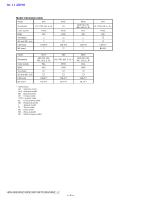
ENGLISH JAPANESE 1-3. METHOD OF COPING WITH SHIFT LENS ERROR (SR7/SR7E/SR8/SR8E) LD-228 BOARD (SIDE A) about 330 msec Note: The length of low section will vary a little depending on the conditions. Fig. 2 Change in output voltage of R5792 on the LD-228 board VC-504 BOARD (SIDE A) R1846 IC1803 R5721 IC5703 R5737 R5792 R1846 IC1803 Fig. 1 Measurement points on the LD-228 board and the VC-504 board 1-3-1. E : 62 : 02 [Abnormality of IC for Steadyshot] Occurred (SR7/SR7E/SR8/SR8E) Order Procedure 1 Turn the power OFF. 2 While measuring with an oscilloscope the output voltage of R5792 in the periphery of IC5703 on the LD-228 board, turn the power ON to check that the output voltage immediately after the power on change as shown in Fig. 2. 3 If the output voltage change as shown in Fig. 2, replace the lens block (Note). If it does not change as shown in Fig. 2, inspect the camera control circuit (IC1803 of VC-504 board) periphery. Note: When the lens block was replaced, execute a necessary adjustment items referring to Service Manual, ADJ. After the adjustment, make sure with the STEADYSHOT turned ON that the steadyshot functions appropriately in the handheld operation. HDR-SR5/SR5C/SR5E/SR7/SR7E/SR8/SR8E_L2 1-3
-
 1
1 -
2
-
3
-
4
-
 5
5 -
 6
6 -
 7
7 -
 8
8 -
 9
9 -
 10
10 -
 11
11 -
 12
12 -
 13
13 -
 14
14 -
 15
15 -
16
-
17
-
18
-
19
-
20
-
21
-
22
-
23
-
24
-
25
-
26
-
27
-
28
-
29
-
30
-
31
-
32
-
33
-
34
-
35
-
36
-
37
-
38
-
39
-
40
-
41
-
42
-
43
-
44
-
45
-
46
-
47
-
48
-
49
-
50
-
51
-
52
-
53
-
54
-
55
-
56
-
57
-
58
-
59
-
60
-
61
-
62
-
63
-
64
-
65
-
66
-
67
-
68
-
69
-
70
-
71
-
72
-
73
-
74
-
75
-
76
-
77
-
78
-
79
-
80
-
81
-
82
-
83
-
84
-
85
-
86
-
87
-
88
-
89
-
90
-
91
-
92
-
93
-
94
-
95
-
96
-
97
-
98
-
99
-
100
-
101
-
102
-
103
-
104
-
105
-
106
-
107
-
108
-
109
-
110
-
111
-
112
-
113
-
114
-
115
-
116
-
117
-
118
 |
 |
